Foam water drainage treatment process

A treatment process, soaking and drainage technology, applied in water/sewage treatment, mining wastewater treatment, biological water/sewage treatment, etc., can solve the problems of peculiar smell, high degree of emulsification, slow defoaming speed, etc., to achieve economical and environmental The effect of win-win, protecting the ecological environment and accelerating the pace of construction

Inactive Publication Date: 2016-09-28
四川光隆环保科技有限公司
View PDF2 Cites 9 Cited by
  • Summary
  • Abstract
  • Description
  • Claims
  • Application Information

AI Technical Summary

Problems solved by technology

It is in the state of emulsion at room temperature, with high degree of emulsification, floating oil on the surface, peculiar smell, easy to foam, large amount of foam, and slow defoaming speed

Method used


Image

  • Foam water drainage treatment process
  • Foam water drainage treatment process
  • Foam water drainage treatment process

Examples


Embodiment 1

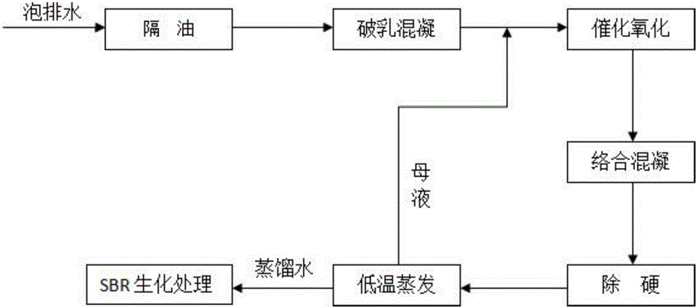
[0028] like figure 1 As shown, the present embodiment provides a bubble drainage treatment process, which includes the following steps in sequence:

[0029] Oil separation: after the soaked water to be treated is static, the liquid is separated, the oil layer is removed, and the water sample of the lower layer is obtained;

[0030] Demulsification and coagulation: take the lower water sample, adjust its pH value to 8, then add demulsifier and coagulant in turn to the lower water sample to produce a large number of flocs, and the lower water sample changes from milky white to khaki, the flocs Floating, the lower layer liquid is turbid, after a period of time, the flocs sink and filter to obtain the filtrate; wherein, the addition amount of the demulsifier is 3g / L; the addition amount of the coagulant solution is 8ml / L, and the amount of the coagulant solution The mass percentage content is 10%;

[0031] Catalytic oxidation: take the filtrate in the demulsification coagulation...

Embodiment 2

[0040]In this embodiment, various parameters in the demulsification coagulation step are screened.

[0041] 1. Screening of pH value

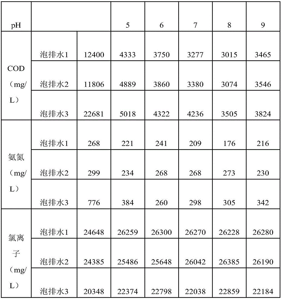
[0042] For beakers numbered 1, 2, 3, 4, and 5, respectively take the lower layer water samples treated by the oil separation step, and adjust the pH values ​​of the lower layer water samples in each numbered beaker to 5, 6, 7, 8, and 9; , the addition of demulsifier is 1g / L, the addition of coagulant solution is 3ml / L, and the mass percentage of coagulant solution is 10%; detection. Among them, the relationship between pH and demulsification coagulation effect is shown in Table 1 below.

[0043] Table 1 Relationship between pH and demulsification coagulation effect

[0044]

[0045]

[0046] It can be seen from the above results that COD first decreases and then increases as the pH value increases. Taking bubble drainage 1 as an example, when pH=9, COD is 3465mg / L, which is higher than 3015mg / L when pH=8, therefore, the optimal pH val...

Embodiment 3

[0053] In this embodiment, various parameters in the catalytic oxidation step are screened.

[0054] 1. Screening of pH value

[0055] For the beakers numbered 1, 2, 3, and 4, take the filtrate obtained in the demulsification and coagulation step respectively, and adjust the pH value of the filtrate in each numbered beaker to 7.5, 8.5, 9.5, and 10.5; then press the mass ratio of 1:20 Add catalyst and oxidant to carry out oxidation reaction, filter after the reaction is complete, and detect the treatment results under different pH conditions. Among them, the catalytic oxidation effects of different pHs are shown in Table 3 below.

[0056] Table 3 Catalytic oxidation effect of different pH

[0057]

[0058] It can be seen from the test results that when the pH is 9.5, the COD in the treated filtrate is the lowest and the NH3-N is low; when the pH is 8.5, the NH3-N in the treated filtrate is the lowest and the COD is at a medium level.

[0059] Therefore, considering the ov...


PUM


Abstract

The invention provides a bubble drainage treatment process, which belongs to the technical field of mining drainage treatment, and comprises the following steps in sequence: oil separation, demulsification coagulation, catalytic oxidation, complex coagulation, hard removal, low temperature evaporation and SBR biochemical treatment. The bubble drainage treatment process provided by the present invention realizes the treatment goals of harmless, reduction and resource utilization of gas extraction wastewater in gas fields; ensures the normal production of gas fields, and does a good job in pollution prevention and energy saving and emission reduction; eliminates environmental hidden dangers, protects Ecological environment of the gas field; speed up the construction of "ecological engineering" of the gas field, promote the harmonious and scientific development of the local economy and the gas field, and achieve a win-win situation for the economy and the environment.

Description

technical field [0001] The invention relates to the technical field of oil recovery drainage treatment, in particular to a bubble drainage treatment process. Background technique [0002] In the middle and late stages of gas field development, formation pressure decreases, edge and bottom water advance, and operations such as fracturing and acidification are implemented, resulting in fluid accumulation at the bottom of the well and in the wellbore, reducing natural gas production or even shutting down due to water flooding. People use various methods to eliminate bottom-hole fluid accumulation, among which the foam drainage gas recovery technology is widely used because of its low cost, quick effect, easy construction, and does not affect the production of gas wells. [0003] The foam drainage gas recovery process is to inject a certain amount of foam drainage agent into the gas well. After the bottom fluid is in contact with the foam drainage agent, a large amount of low-de...

Claims


Application Information

Patent Timeline
Patent Type & Authority Applications(China)
IPC IPC(8): C02F9/14C02F103/10
CPCC02F9/00C02F1/001C02F1/048C02F1/06C02F1/40C02F1/52C02F1/725C02F3/1263C02F2103/10
Inventor 向荣
Owner 四川光隆环保科技有限公司
Why Eureka
Try Eureka