Cascaded gain-modulated dual-wavelength mid-infrared pulsed fiber laser

A fiber laser, dual-wavelength technology, used in lasers, laser parts, phonon exciters, etc., can solve the problems of high cost, complex structure, small size, etc., and achieve simple structure, strong portability, and convenient use. Effect

Active Publication Date: 2019-02-19
UNIV OF ELECTRONIC SCI & TECH OF CHINA
View PDF5 Cites 0 Cited by
  • Summary
  • Abstract
  • Description
  • Claims
  • Application Information

AI Technical Summary

Problems solved by technology

Recently, it has been reported that dual-wavelength mid-infrared pulsed laser output can be achieved through active Q-switching and active Q-switching guided gain modulation, and the pulse energy can reach the level of tens of μJ. The introduced modulation crystal makes the structure of the method complex, and makes the fiber laser lose its inherent flexibility, compactness, small size and other advantages, and the cost is also very expensive

Method used


Image

  • Cascaded gain-modulated dual-wavelength mid-infrared pulsed fiber laser
  • Cascaded gain-modulated dual-wavelength mid-infrared pulsed fiber laser
  • Cascaded gain-modulated dual-wavelength mid-infrared pulsed fiber laser

Examples


specific Embodiment 1

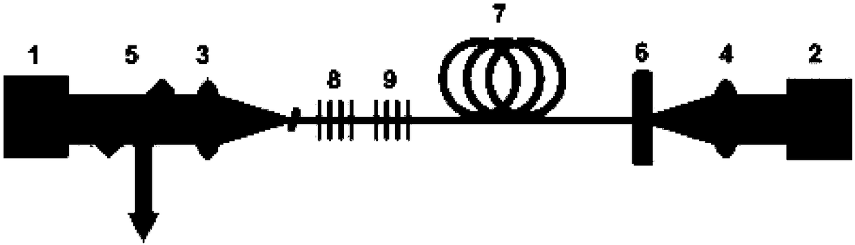
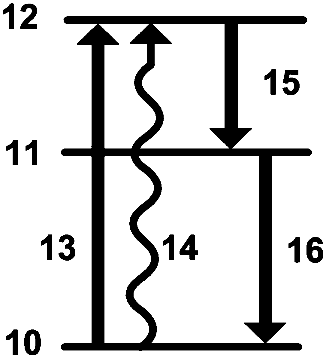
[0043] Such asfigure 1 , figure 2 As shown, the 976nm continuous pump light output by the first semiconductor optical pump source 1 is coupled into the Er-doped 3+ (Positive trivalent erbium ion) in the fluoride optical fiber 7, the 976nm pulsed pumping light that the second semiconductor optical pumping source 2 outputs is coupled into the Er doped with the second coupling mirror 4 3+ The fluoride fiber 7, doped with Er 3+ On the left side of the fluoride optical fiber 7, the first fiber Bragg grating 8 and the second fiber Bragg grating 9 are sequentially written, the central wavelengths are 2.8 μm and 1.6 μm, respectively, and Er doped 3+ The right end of the fluoride optical fiber 7 is vertically connected to the second dichroic mirror 6, the first fiber grating 8 and the second dichroic mirror 6 form a 2.8 μm laser resonator cavity, and the second fiber grating 9 and the second dichroic mirror 6 form a 1.6 μm laser resonant cavity, the first dichroic mirror 5 is placed...

specific Embodiment 2

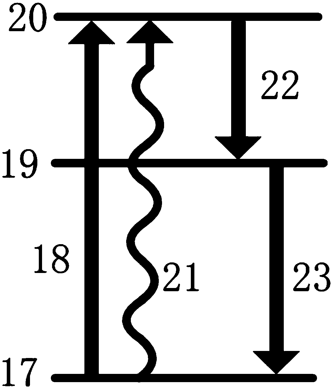
[0047] Such as figure 1 , image 3 As shown, the 1150nm continuous pump light output by the first semiconductor optical pumping source 1 is coupled into the Ho-doped 3+ (Positive trivalent holmium ions) in the fluoride optical fiber 7, the 1150nm pulsed pump light output by the second semiconductor optical pump source 2 is coupled into the Ho-doped optical fiber through the second coupling mirror 4 3+ The fluoride fiber 7, doped with Ho 3+ On the left side of the fluoride optical fiber 7, the first fiber Bragg grating 8 and the second fiber Bragg grating 9 are sequentially written, the center wavelengths are 3.0 μm and 2.1 μm, respectively, doped with Ho 3+ The right end of the fluoride optical fiber 7 is vertically connected to the second dichroic mirror 6, the first fiber grating 8 and the second dichroic mirror 6 form a 3.0 μm laser resonator cavity, and the second fiber grating 9 and the second dichroic mirror 6 form a 2.1 μm laser resonant cavity, the first dichroic mi...


PUM

PropertyMeasurementUnit
Slopeaaaaaaaaaa

Abstract

The invention discloses a cascaded gain-modulated dual-wavelength mid-infrared pulse fiber laser, which comprises a first semiconductor optical pumping source, a first dichromatic mirror, a first coupling mirror, and fluoride doped with Er3+ or Ho3+ connected in sequence fiber, a second dichroic mirror, a second coupling mirror, and a second semiconductor optical pumping source, and between the first coupling mirror and the fluoride fiber doped with Er3+ or Ho3+, a first fiber grating and a second Fiber Bragg grating; the second dichroic mirror, the first fiber grating and the second fiber grating form a resonant cavity, and the second dichroic mirror is vertically connected to the end of the Er3+ or Ho3+ fluoride fiber doped as a resonant cavity feedback; A fiber grating and a second fiber grating serve as a resonant cavity for feedback and output coupling. The invention has simple structure and strong portability, no active modulation device with complicated structure is needed in the resonant cavity, the requirement for output parameters is low, and the use is convenient.

Description

technical field [0001] The invention relates to a mid-infrared pulsed fiber laser, which belongs to the field of fiber lasers, and more specifically relates to a cascaded gain-modulated dual-wavelength mid-infrared pulsed fiber laser. Background technique [0002] The 2-5μm mid-infrared high-energy pulsed laser source has important application prospects in the fields of biomedicine (laser lithotripsy, soft tissue cutting), material processing (organic polymers, ceramics, plastics), national defense (laser countermeasures), and is therefore favored by people. extensive attention. As a new type of laser, fiber laser has a series of significant advantages such as high conversion efficiency, good beam quality, good heat dissipation, and easy integration. Therefore, the development of high-energy mid-infrared fiber laser has important scientific significance and application value. At present, there are two main methods for realizing high-energy mid-infrared pulsed fiber laser ou...

Claims


Application Information

Patent Timeline
IPC IPC(8): H01S3/08H01S3/1055H01S3/067H01S3/094
CPCH01S3/06716H01S3/08009H01S3/094H01S3/1055
Inventor 李剑峰罗鸿禹翟波胡韵箫刘永
Owner UNIV OF ELECTRONIC SCI & TECH OF CHINA
Why Eureka
Try Eureka