Secondary-side control method and secondary-side control circuit of switching power supply

A technology of control circuit and switching power supply, which is applied in control/regulation system, high-efficiency power electronic conversion, electrical components, etc. It can solve problems such as complex timing, optimized performance, and poor dynamic response, so as to improve accuracy and load adjustment rate, and speed up The effect of dynamic response and good dynamic performance

Active Publication Date: 2016-10-12
SHENZHEN NANYUN MICROELECTRONICS CO LTD
View PDF8 Cites 31 Cited by
  • Summary
  • Abstract
  • Description
  • Claims
  • Application Information

AI Technical Summary

Problems solved by technology

However, the disadvantage of the primary side feedback control method is that the load regulation rate of the output voltage of the power supply is not good, and the dynamic response is poor.
However, the patent still belongs to the primary side control in essence. The added secondary side circuit provides two kinds of feedback information, and only optimizes the performance at light load and no load.
Patent CN104578826 realizes constant current and constant voltage control by the secondary side in the full load range. However, the secondary side chip of this patent is directly powered by the output voltage of the power supply, and the output voltage needs to be established to the starting point of the chip to realize feedback and normal operation. General charging Applications such as converters need to have the function of constant current in the stage of output voltage establishment, so this solution is not practical enough
Another patent CN103460583 adopts secondary side PWM control, which has better performance, but needs to pre-charge the energy storage circuit to make the power output normally established, and the timing is more complicated
The patent US20100254443 provides a common digital power control method, the circuit is complex, and high-precision analog-to-digital and digital-to-analog conversion circuits are required

Method used


Image

  • Secondary-side control method and secondary-side control circuit of switching power supply
  • Secondary-side control method and secondary-side control circuit of switching power supply
  • Secondary-side control method and secondary-side control circuit of switching power supply

Examples


Embodiment 1

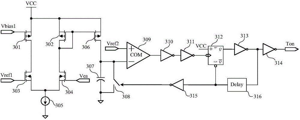
[0031] The PFM control circuit in the master control unit of the secondary side is responsible for the frequency modulation of the turn-on signal, such as image 3 As shown, a PFM control circuit includes: PMOS tube 301, PMOS tube 302, PMOS tube 306, NMOS tube 303, NMOS tube 304, current source 305, capacitor 307, switch 308, comparator 309, inverter 310, inverter Phaser 311, D flip-flop 312, inverter 313, inverter 314, inverter 315, and delayer 316. The source terminals of the PMOS transistors 301, 302, and 306 are connected to the internal power supply voltage, the gate terminal of 301 is connected to the bias voltage Vbias1, the drain terminal is connected to the drain terminal of the NMOS transistor 303; the drain terminal of 302 is connected to its own drain terminal and the The gate terminal; the drain terminal of 306 is connected to the upper plate of the capacitor 307; the gate terminal of the NMOS tube 303 is connected to the reference voltage Vref1, and the source term...

Embodiment 2

[0045] The current-limiting voltage generation circuit of the PWM control circuit in the first embodiment can also be implemented in another way, such as Figure 5 As shown, another current-limiting voltage generation circuit includes an inverter 501, an AND gate 503, a high-frequency oscillator 502, an M-bit subtraction counter 504, an M digital-to-analog converter 505, and a buffer 506. The input terminal of the inverter 501 receives the narrow pulse turn-on signal Tonp, and the output terminal is connected to one input terminal of the AND gate 503; the other input terminal of the AND gate 503 is connected to the output terminal of the high frequency oscillator 502, and the output terminal is connected to M The input terminal of the bit subtraction counter; the output terminal of the M bit subtraction counter 504 is connected to the input terminal of the M digital to analog converter 505; the output terminal of the M digital to analog converter is connected to the positive inpu...


PUM


Abstract

The invention provides a switching power supply, especially a secondary-side control method and a secondary-side control circuit of an isolated switching power supply. According to the method and the circuit, an error amplifier is installed at a secondary side, the output voltage of the power supply is sampled and an error signal is generated, and the error signal is modulated into an opening signal of different frequencies to realize PFM (Pulse Frequency Modulation). The opening signal is transmitted to a primary side to open a main power tube, different current limiting voltage is generated at the primary side according to the frequency of the opening signal, and the main power tube is closed at the current limiting voltage to realize PWM. Through the method and the circuit of the invention, the precision of output voltage and the load regulation rate are improved, good dynamic performance is achieved, synchronous rectification is easy to realize, and the no-load power consumption is reduced.

Description

Technical field [0001] The invention relates to a loop control method and circuit of a switching power supply, in particular to a switching power supply capable of improving the output accuracy and load regulation rate of an isolated switching power supply, reducing light load and no-load power consumption, speeding up dynamic response, and facilitating synchronous rectification The secondary side control method and circuit. Background technique [0002] Primary-side feedback switching power supplies are widely used in chargers, power adapters and other fields due to their small size, simple control, and low cost. However, the disadvantage of the primary-side feedback control method is that the load regulation rate of the output voltage of the power supply is not good, and the dynamic response is poor. Such as figure 1 Shown is the typical architecture of the primary-side feedback control circuit. The control chip realizes constant current control by detecting the timing of the...

Claims


Application Information

Patent Timeline
Patent Type & Authority Applications(China)
IPC IPC(8): H02M7/217H02M3/335
CPCH02M3/33561H02M3/33592H02M7/2176H02M1/0032Y02B70/10
Inventor 於昌虎唐盛斌肖华
Owner SHENZHEN NANYUN MICROELECTRONICS CO LTD
Why Eureka
Try Eureka