Carbon dioxide capturing and liquefying process stepwise utilizing smoke waste heat

A carbon dioxide and flue gas waste heat technology, applied in the field of separation, can solve problems such as increasing the complexity of the process, and achieve the effect of avoiding adsorption and dehydration units, reducing dehydration requirements, and simplifying the process flow

Active Publication Date: 2016-10-26
DALIAN UNIV OF TECH
View PDF4 Cites 22 Cited by
  • Summary
  • Abstract
  • Description
  • Claims
  • Application Information

AI Technical Summary

Problems solved by technology

Obviously, the currently used carbon dioxide compression liquefaction process mainly has a large amount of c

Method used


Image

  • Carbon dioxide capturing and liquefying process stepwise utilizing smoke waste heat
  • Carbon dioxide capturing and liquefying process stepwise utilizing smoke waste heat
  • Carbon dioxide capturing and liquefying process stepwise utilizing smoke waste heat

Examples


Embodiment 1

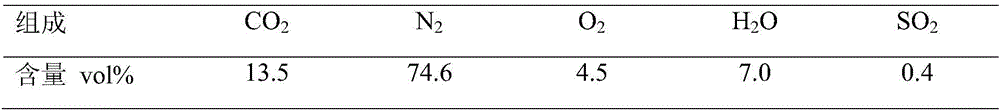
[0024] Table 1 Average composition of flue gas in a 600MW coal-fired power plant

[0025]

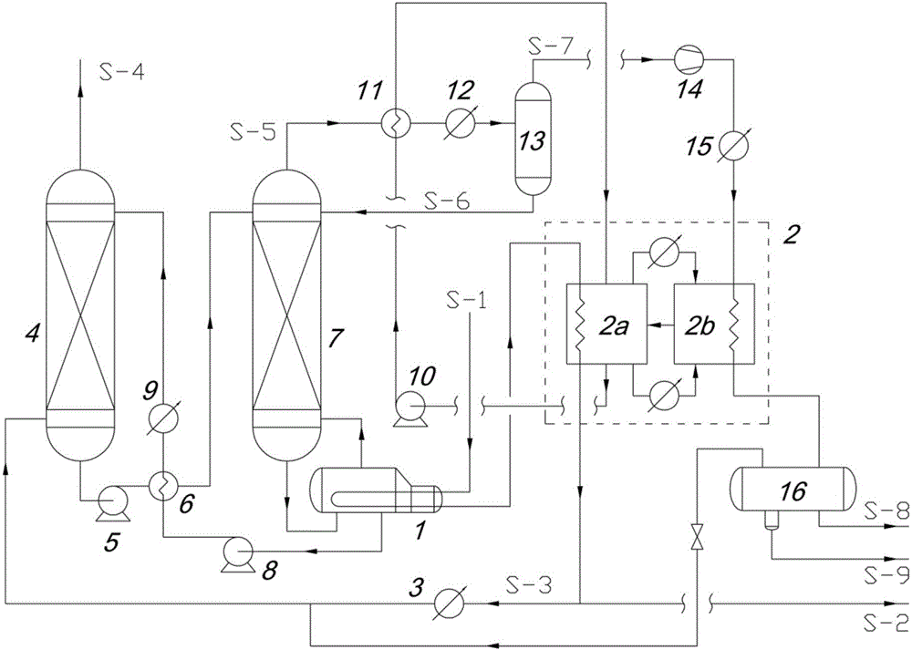
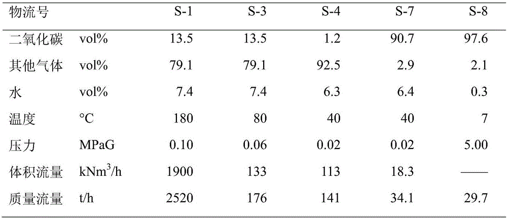
[0026] This embodiment is aimed at the flue gas (flow rate 190×10 4 N m 3 / h, the content of carbon dioxide is 13.5vol%, and the temperature is 180°C), the carbon dioxide capture liquefaction process of the present invention is adopted, and the waste heat of the flue gas is used in stages to separate the carbon dioxide from part of the flue gas to produce liquid crude carbon dioxide.

[0027] Such as figure 1 As shown, flue gas S-1 pretreated by dust removal, desulfurization, denitrification, etc., is sent to the reboiler 1 by the blower, and exchanges heat with the absorbent to be regenerated; then, it enters the steam generator 2a of the absorption refrigeration system 2 , exchange heat with the dilute solution in the refrigeration system; subsequently, a part of S-2 is directly discharged into the atmosphere, and another part of S-3 enters the first cooler 3, and enters the absor...

Embodiment 2

[0033] Table 3 Average composition of flue gas in a 500MW coal-fired power plant (excessive air control)

[0034]

[0035] This embodiment is aimed at the flue gas produced by a certain 500MW coal-fired power plant (with air excess control, flow rate 145×10 4 N m 3 / h, carbon dioxide content 14.6vol%, temperature 200°C), using the carbon dioxide capture liquefaction process of the present invention, cascade use of flue gas waste heat, part of the flue gas is subjected to carbon dioxide separation treatment, and liquid crude carbon dioxide is produced. The technological process that this embodiment adopts sees figure 1 , whose details are described in Example 1.

[0036] In this implementation case, using the process of the present invention, the regeneration tower 7 does not require additional steam, and only by utilizing the waste heat (200→80°C) of all the flue gas of the coal-fired power plant, it can achieve 8.7% of the total flue gas Liquefaction with carbon dioxide...

Embodiment 3

[0040] Table 5 Average composition of flue gas in a 600MW natural gas power generation project

[0041]

[0042] This embodiment is aimed at the flue gas produced by a 600MW coal-fired power plant (with air excess control, flow rate 260×10 4 N m 3 / h, carbon dioxide content 8.0vol%, temperature 200°C), the carbon dioxide capture liquefaction process of the present invention is adopted, the waste heat of the flue gas is used in stages, and carbon dioxide is separated from part of the flue gas to produce liquid crude carbon dioxide. The technological process that this embodiment adopts sees figure 1 , whose details are described in Example 1.

[0043] In this implementation case, using the process of the present invention, the regeneration tower 7 does not need additional steam, and only by using the waste heat (200→80°C) of all the flue gas of the coal-fired power plant, it can achieve 17.3% of the total flue gas Liquefaction with carbon dioxide capture. The process simu...


PUM


Abstract

The invention provides a carbon dioxide capturing and liquefying process stepwise utilizing smoke waste heat and belongs to the technical field of separation. The process is based on chemical absorption, absorption refrigeration and compression condensation; by stepwise utilizing the smoke waste heat, the smoke waste heat is used as a heat source for absorbent regeneration and then used as a heat source for absorption refrigeration, heat consumed during absorbent regeneration is utilized for the second time, and low-temperature heat carried by carbon dioxide at the top of a regeneration tower is used as a heat source for absorption refrigeration, so that cost of carbon dioxide capturing and liquefying is reduced effectively, recycling of carbon dioxide and implementing of carbon emission reduction are facilitated. The process has the advantages that steam consumption during absorbent regeneration is avoided, compression work consumption during liquefying is reduced, and 1.5 tons of steam 20kWh can be saved by each ton of carbon dioxide; by optimizing and designing the refrigerating and liquefying process, liquefying temperature of carbon dioxide is increased to higher than 5 DEG C, freeze blocking and hydrate forming are avoided, and the dewatering process is simplified.

Description

technical field [0001] The invention relates to a carbon dioxide capture liquefaction process for efficiently utilizing waste heat of flue gas to reduce energy consumption of separation, and belongs to the technical field of separation. In the process of the present invention, the low-grade heat carried by the flue gas is firstly heated to regenerate the chemical absorbent for capturing carbon dioxide, and then converted into cold energy through the absorption refrigeration system for the condensation and liquefaction of high-concentration carbon dioxide. Through the cascaded utilization of flue gas waste heat, the process effectively reduces the cost of carbon dioxide capture and liquefaction. Background technique [0002] Carbon dioxide is the most important anthropogenic greenhouse gas, contributing as much as 70% to the increase in global temperature. The large-scale use of fossil fuels in the energy and industrial sectors is the main anthropogenic source of concentrate...

Claims


Application Information

Patent Timeline
IPC IPC(8): B01D53/78B01D53/96B01D53/62B01D53/73B01D53/00F25B15/02F25B27/02F25J1/00
CPCB01D53/002B01D53/62B01D53/73B01D53/78B01D53/96B01D2252/20478F25B15/02F25B27/02F25J1/0027F25J2210/70F25J2215/80Y02A30/274Y02C20/40
Inventor 阮雪华辛月贺高红肖武代岩焉晓明张宁
Owner DALIAN UNIV OF TECH
Why Eureka
Try Eureka