Method for directly writing graphene pattern on nonmetal surface by laser

A non-metallic surface, graphene technology, applied in electrical components, semiconductor/solid-state device manufacturing, circuits, etc., can solve the problems of inability to synchronize graphene preparation and patterning, poor graphene performance, etc., to achieve easy operation, The effect of simple operation and safe preparation process

Inactive Publication Date: 2016-10-26
725TH RES INST OF CHINA SHIPBUILDING INDAL CORP
View PDF4 Cites 22 Cited by
  • Summary
  • Abstract
  • Description
  • Claims
  • Application Information

AI Technical Summary

Problems solved by technology

These two scientific research results have confirmed the feasibility of graphene generation under the condition of metal-free catalysts, but there are also the following problems: a) the performance of graphene currently prepared is not good; b) graphene preparation and patterning cannot be realized simultaneously change

Method used


Image

  • Method for directly writing graphene pattern on nonmetal surface by laser
  • Method for directly writing graphene pattern on nonmetal surface by laser
  • Method for directly writing graphene pattern on nonmetal surface by laser

Examples


preparation example Construction

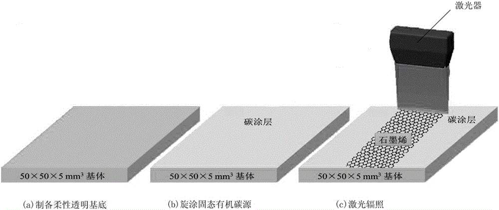
[0026] figure 1 It is a schematic diagram of the preparation process of an embodiment of the present invention. refer to figure 1 , the laser of the present invention directly writes the graphene pattern method on non-metallic surface and comprises the steps:

[0027] Step 1, preparing a polydimethylsiloxane base;

[0028] Step 2. Spin coating the solid organic carbon source: use a spin coater to evenly spin coat the solid organic carbon source on the surface of the flexible transparent substrate described in step 1 at a set speed and spin coating time to obtain a uniform carbon coating;

[0029] Step 3. Laser irradiation: under the protection of an inert gas, use an ultrashort pulse laser beam to move the surface of the carbon coating obtained in step 2 according to the designed pattern, and irradiate the carbon coating. The organic carbon source of the carbon coating is in the laser Under the irradiation of light, the long carbon chain is cracked into short carbon chain, ...

Embodiment 1

[0034] In this embodiment, a femtosecond laser is used to directly write graphene patterns on polydimethylsiloxane (PDMS). Specific steps are as follows:

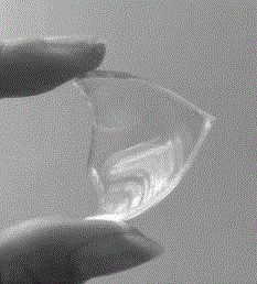
[0035] Step 1. Preparation of PDMS substrate

[0036] First, mix dimethyl vinyl polysiloxane and silane coupling agent in a ratio of 10:1, stir the mixed solution thoroughly to generate bubbles, then put the mixed solution in an ultrasonic cleaning instrument for 10 minutes, After the air bubbles completely disappeared, pour the mixed solution into a mold with a size of 5cm×5cm×5cm. Finally, put the mold containing the mixed solution in an oven at 80°C for 7 hours to solidify the mixed solution to obtain Flexible transparent PDMS substrates, such as figure 2 shown.

[0037] Step 2, coating carbon source sucrose on the PDMS substrate prepared in step 1

[0038] Grind the sucrose particles to a particle size of 20 μm and mix them with alcohol at a ratio of 10g:16ml to form a suspension. Use a spin coater to coat the abov...


PUM

PropertyMeasurementUnit
thicknessaaaaaaaaaa
wavelengthaaaaaaaaaa
diameteraaaaaaaaaa

Abstract

The invention provides a method for directly writing a graphene pattern on a nonmetal surface by laser. The method comprises the following steps: step 1, preparing a flexible transparent substrate; step 2, spin coating a solid organic carbon source: using a spin coating machine to evenly coat the solid organic carbon source on the surface of the flexible transparent substrate in step 1 at a set rotating speed and a set spin coating time to acquire an even carbon coating; and step 3, laser irradiation: moving an ultra short pulsed laser beam on the surface of the carbon coating acquired in step 2 according to the designed pattern under the protection of an inert gas to irradiate the carbon coating, so as to form graphene with the set pattern on the surface of the flexible transparent substrate. According to the method provided by the invention, by means of the property of high power density of laser and the characteristics of fast temperature rise and fast cooling, the growth and patterning of the graphene can be accomplished within a very short period of time.

Description

technical field [0001] The invention belongs to the field of novel carbon nanomaterials, and in particular relates to a method for directly writing graphene patterns on a non-metallic surface with a laser. Background technique [0002] Flexible devices are the key devices to realize wearable electronic devices and intelligent era. At present, most mature transparent electrodes are made of indium tin oxide (ITO). This is because ITO has high electrical conductivity and can ensure good light transmission. However, ITO has poor mechanical properties and cannot withstand bending and is easy to destroyed. The emergence of graphene provides a better choice for flexible and transparent devices. Its ultra-high electrical conductivity, light transmission and mechanical properties make graphene incomparably superior in this field. [0003] Most of the current graphene electronic devices are made by a three-step method, including three steps of preparation, transfer and patterning. T...

Claims


Application Information

Patent Timeline
Patent Type & Authority Applications(China)
IPC IPC(8): H01L21/02
CPCH01L21/02697
Inventor 叶晓慧苏孟兴陈迪春
Owner 725TH RES INST OF CHINA SHIPBUILDING INDAL CORP
Why Eureka
Try Eureka