Cooling tower for cascaded cooling water preparation with composite structure

A composite structure and cooling tower technology, applied in the field of cooling towers, can solve the problems of water loss, polluted cooling water, easy corrosion and damage, etc., and achieve the effects of easy replacement, space saving, good corrosion resistance and flame retardancy

Active Publication Date: 2018-05-15
ZHEJIANG JINLING REFRIGERATION ENG
View PDF8 Cites 0 Cited by
  • Summary
  • Abstract
  • Description
  • Claims
  • Application Information

AI Technical Summary

Problems solved by technology

[0003] Since the fan motor and blades of the open cooling tower are exposed to the air, the noise during operation is relatively large and it is easy to rust and damage; in addition, because it is an open system, the cooling tower will produce water drift during operation, causing The loss of water and the pollution of the surrounding air environment require frequent replenishment of water during operation, and the open environment will also pollute the cooling water and reduce the water quality, and external debris can easily enter the cooling water and cause water pollution; The cooling water pressure loss is higher than that of the closed cooling tower
[0004] A large number of copper coils with high heat transfer performance but expensive are used in closed cooling towers, so the price of closed cooling towers is generally higher; in practical applications, closed cooling towers have outstanding energy-saving and consumption-reducing characteristics and a long service life If properly maintained) and the advantages of stable cooling performance; however, in the northern region, the temperature in winter is low, if no effective antifreeze measures are taken, it may cause local cracking of the cooler

Method used


Image

  • Cooling tower for cascaded cooling water preparation with composite structure
  • Cooling tower for cascaded cooling water preparation with composite structure

Examples


Embodiment Construction

[0030] The present invention will be described in detail below in conjunction with the accompanying drawings and specific embodiments.

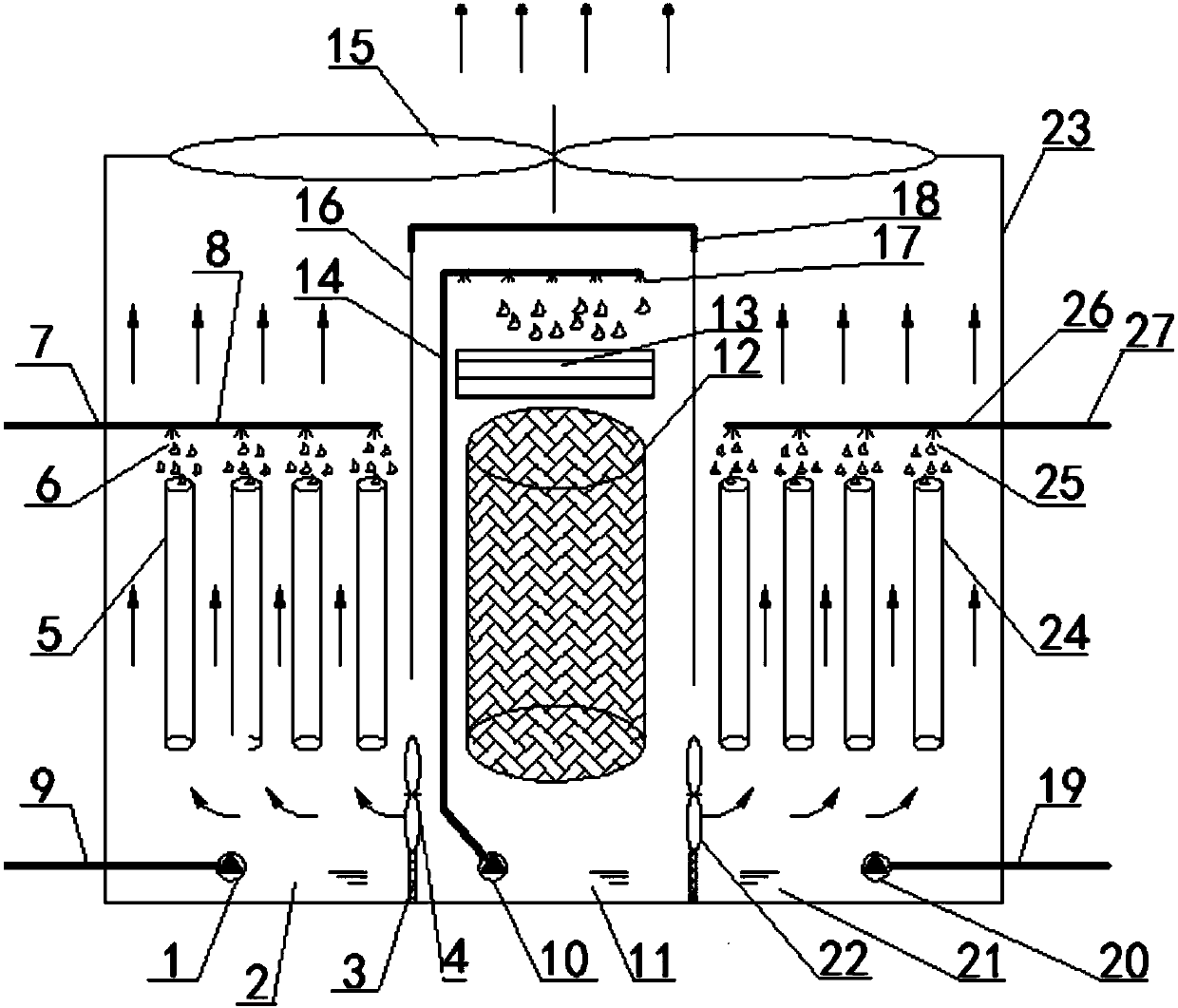
[0031] The present invention has the cascaded cooling water of compound structure to prepare cooling tower, as figure 1 As shown, a cooling tower housing 23 is included, the top of the cooling tower housing 23 is provided with an air outlet, and the middle part of the cooling tower housing 23 is provided with a packing type direct evaporative cooling unit, and the left and right sides of the packing type direct evaporative cooling unit The first vertical pipe type indirect evaporative cooling unit and the second vertical pipe type indirect evaporative cooling unit are respectively arranged on the right sides; the first vertical pipe type indirect evaporative cooling unit and the second vertical pipe type indirect evaporative cooling unit are connected with the cooling tower shell The chiller system outside the body 23 is connected.

[0032] ...


PUM


Abstract

The invention discloses a stepped temperature-decrease cooling water preparation cooling tower of a composite structure. The stepped temperature-decrease cooling water preparation cooling tower comprises a cooling tower shell. The top of the cooling tower shell is provided with an air outlet. A filler type direct evaporation cooling unit is arranged in the middle of the cooling tower shell. A first vertical tube type indirect evaporation cooling unit and a second vertical tube type indirect evaporation cooling unit are arranged on the left side and the right side of the filler type direct evaporation cooling unit respectively. The first vertical tube type indirect evaporation cooling unit and the second vertical tube type indirect evaporation cooling unit are both connected with a water chilling unit system arranged outside the cooling tower shell. According to the stepped temperature-decrease cooling water preparation cooling tower, water cooling temperature decrease and air cooling temperature decrease are combined in cooperation with a stepped temperature decrease mode, and thus the temperature decrease efficiency of the cooling tower can be improved, energy consumption can be reduced, and cooling temperature with lower temperature can be prepared; and the filler type direct evaporation cooling unit and the two vertical tube type indirect evaporation cooling units are arranged inside the cooling tower and can meet the requirements of different seasons, and the cooling tower has very important significance in application and popularization.

Description

technical field [0001] The invention belongs to the technical field of cooling towers, and in particular relates to a cooling tower with a composite structure for preparing cooling water by cascade cooling. Background technique [0002] At present, commonly used cooling towers are generally divided into two types: open cooling towers and closed cooling towers, both of which use air cooling mode for cooling. [0003] Since the fan motor and blades of the open cooling tower are exposed to the air, the noise during operation is relatively large and it is easy to rust and damage; in addition, because it is an open system, the cooling tower will produce water drift during operation, causing The loss of water and the pollution of the surrounding air environment require frequent replenishment of water during operation, and the open environment will also pollute the cooling water and reduce the water quality, and external debris can easily enter the cooling water and cause water pol...

Claims


Application Information

Patent Timeline
IPC IPC(8): F28C1/14F28F25/06F28F25/08F28F27/00
CPCF28C1/14F28F25/06F28F25/08F28F27/003
Inventor 黄翔杜冬阳高源基
Owner ZHEJIANG JINLING REFRIGERATION ENG
Why Eureka
Try Eureka