Turning light-splitting unit, and endoscope optical imaging system and imaging method

A technology of optical imaging system and beam splitting unit, which is applied in the field of minimally invasive, can solve the problems of high cost of image sensors, high computing requirements, and large structure, and achieve the effect of low computing requirements, simple operation, and a small number of prisms

Active Publication Date: 2016-11-09
SHANGHAI KINETIC MEDICAL
View PDF10 Cites 4 Cited by
  • Summary
  • Abstract
  • Description
  • Claims
  • Application Information

AI Technical Summary

Problems solved by technology

Although this method avoids the problem of out-of-focus in the simultaneous imaging of visible light and near-infrared fluorescence, and improves the resolution of the image, the cost of the four image sensors is high, and the color and fluorescence images need to be synthesized before outputting, which requires the calculation of the software. High, and the structure is huge and complex

Method used


Image

  • Turning light-splitting unit, and endoscope optical imaging system and imaging method
  • Turning light-splitting unit, and endoscope optical imaging system and imaging method
  • Turning light-splitting unit, and endoscope optical imaging system and imaging method

Examples


Embodiment 1

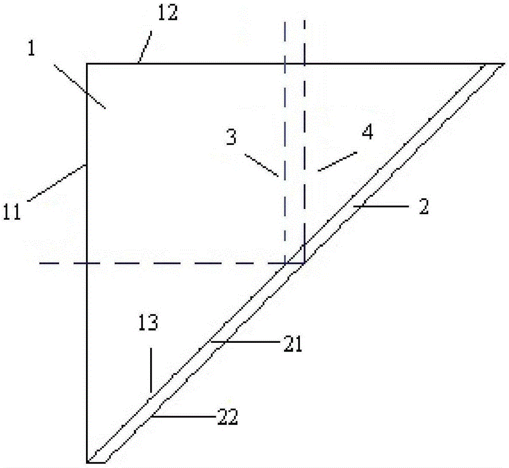
[0064] Embodiment 1: turning beam splitting unit

[0065] combine figure 1 , this embodiment describes in detail the turning spectroscopic unit of the present invention, which is used to split and recombine incident light of two different wavelengths: the first wavelength light and the second wavelength light, so that the first wavelength light and the second wavelength light The optical paths of the wavelength light are different, so that the positions of the imaging focal planes of the first wavelength light and the second wavelength light are consistent. Specifically, its structural diagram is as follows figure 1 As shown, it includes: an isosceles rectangular prism 1 and a plate glass 2 , the front surface of the plate glass 2 is glued together with the slope of the isosceles rectangular prism 1 , and in different embodiments, it can also be fixed by other means. The first wavelength light 3 and the second wavelength light 4 are transmitted into the isosceles rectangular...

Embodiment 2

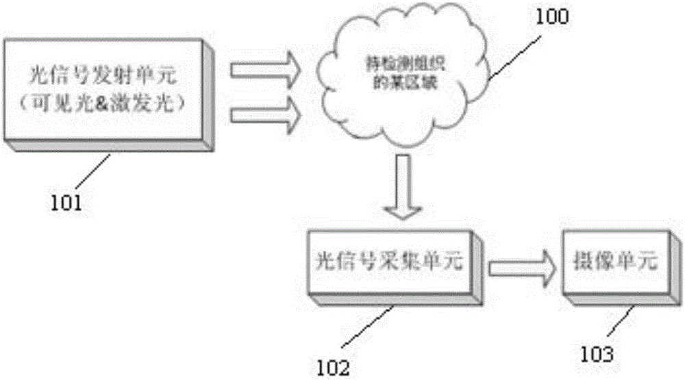
[0068] Embodiment 2: Endoscopic optical imaging system

[0069] combine figure 2 , this embodiment describes the endoscope optical system of the present invention in detail, and its structural schematic diagram is as follows figure 2 As shown, it includes: an optical signal transmitting unit 101 , an optical signal collecting unit 102 and a camera unit 103 . Among them, the optical signal transmitting unit 101 is used to emit visible light (400nm-700nm) and near-infrared excitation light (such as 808nm near-infrared laser) to a certain area 100 of the tissue to be detected. The near-infrared excitation light excites and emits near-infrared fluorescence (820nm-850nm). Visible light, near-infrared fluorescence and near-infrared excitation light all enter the optical signal acquisition unit 102, and the optical signal acquisition unit 102 processes the three kinds of light, such as: eliminating Aberration, changing the direction of the optical path to the required direction, ...

Embodiment 3

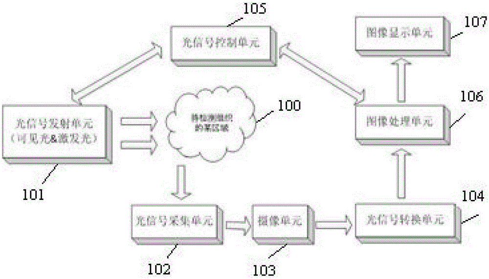
[0070] Embodiment 3: Endoscopic optical imaging system

[0071] This embodiment is an improvement made on the basis of Embodiment 2, which adds an optical signal conversion unit 104, an optical signal control unit 105, an image processing unit 106, and an image display unit 107 on the basis of Embodiment 2. Its structure Schematic such as image 3 As shown, wherein the optical signal conversion unit 104 is used to convert the visible light and near-infrared fluorescence received by the image sensor 1032 into corresponding electrical signals, and process them into video data; the image processing unit 106 is used to receive the optical signal conversion unit 104 to obtain video data; the optical signal control unit 105 is used to control the optical signal transmitting unit 101 to emit visible light and near-infrared excitation light, and is also used to set the visible light mode or the near-infrared fluorescent mode, and the image processing unit 106 is configured according t...


PUM


Abstract

The invention discloses a turning light-splitting unit, and an endoscope optical imaging system and imaging method. The turning light-splitting unit is used for enabling the positions of imaging focal planes of light with different wavelengths to be consistent. The imaging system comprises a light signal transmitting unit, a light signal collection unit, and a camera unit. The light signal transmitting unit transmits visible light and near infrared exciting light to a to-be-detected tissue. The light signal collection unit collects the visible light reflected by the to-be-detected tissue and the near infrared fluorescence emitted by excitation. The camera unit receives two types of light collected by the light signal collection unit, and enables the positions of imaging focal planes of two types of light to be consistent. The imaging method comprises the steps: transmitting visible light and near infrared exciting light to the to-be-detected tissue; collecting the visible light reflected by the to-be-detected tissue and the near infrared fluorescence emitted by excitation; splitting two types of light, converging the two types of light, and enabling the positions of imaging focal planes of two types of light to be consistent. The system is simple in structure, is small in size, and is low in manufacture cost. The system can output color and fluorescence images at the same time, and is low in requirements for the operation capability of software.

Description

technical field [0001] The invention relates to the field of minimally invasive technology, in particular to a turning beam splitting unit, an endoscope optical imaging system, and an imaging method. Background technique [0002] In recent years, as the near-infrared fluorescent contrast agent ICG (indocyanine green) is used in the research of ocular blood vessels, especially choroidal blood vessels, the diagnosis of malignant tumors, the determination of tumor margins, and the detection of tumor sentinel lymph nodes, etc., in minimally invasive diagnosis and The field of surgery has developed rapidly, and at the same time, new requirements have been put forward for the supporting medical endoscopes. Existing medical endoscopes generally use the visible light spectrum (400nm-700nm), in this spectral range, the endoscope system can meet the requirements of clear imaging. However, near-infrared fluorescence contrast imaging uses near-infrared fluorescence spectrum (820nm-850n...

Claims


Application Information

Patent Timeline
Patent Type & Authority Applications(China)
IPC IPC(8): G02B27/10A61B1/05A61B1/04A61B1/00
CPCA61B1/00163A61B1/043A61B1/05G02B27/1006
Inventor 张升进唐伟蔣寅杰
Owner SHANGHAI KINETIC MEDICAL
Why Eureka
Try Eureka