Bias voltage full-automatic temperature compensation system for APD array chip

An APD array, temperature compensation technology, applied in the control/regulation system, regulating electrical variables, instruments, etc., can solve the problems of small voltage range of high-voltage modules, manual adjustment, inconvenient adjustment, etc., to achieve simple circuit structure and ensure consistency , the effect of high sensitivity

Inactive Publication Date: 2016-11-09
GUILIN UNIVERSITY OF TECHNOLOGY
View PDF5 Cites 8 Cited by
  • Summary
  • Abstract
  • Description
  • Claims
  • Application Information

AI Technical Summary

Problems solved by technology

[0003] "Optical Communication Technology" Journal 12, 2014 "Design of APD Bias Temperature Compensation Circuit Based on ADL5317 and LM35"; "Circuit Design", both disclose the design of the APD bias temperature compensation circuit. The disadvantages are: it is necessary to manually adjust the parameters of multiple components in the circuit, the voltage range of the high voltage module is small, and the adjustment is inconvenient
"Optics and Optoelectronics Technology", Issue 4, 2013, "APD Numerical Control Bias Circuit with Temperature Compensation"; "Industrial Control Computer", Volume 25, No. 3, 2012, "Design of Numerical Control Bias Source for Avalanche Photodiode Based on DSP" , their shortcomings are: although a microcontroller is used, some components of the high-voltage module still need to be adjusted manually; and the temperature measurement circuit is more complicated
[0004] None of the existing temperature compensation methods are aimed at APD array chips, they are all limited to a single APD, and some circuit parameters need to be adjusted manually, and automatic temperature compensation has not been realized.

Method used


Image

  • Bias voltage full-automatic temperature compensation system for APD array chip
  • Bias voltage full-automatic temperature compensation system for APD array chip
  • Bias voltage full-automatic temperature compensation system for APD array chip

Examples


Embodiment

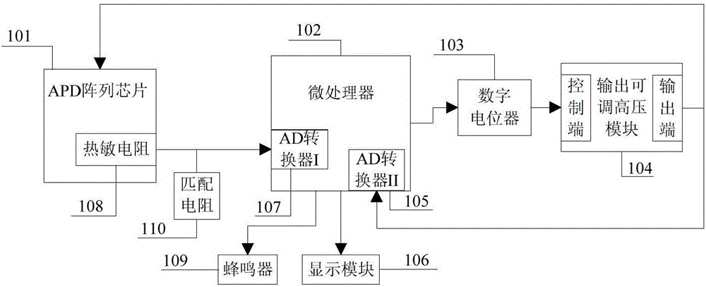
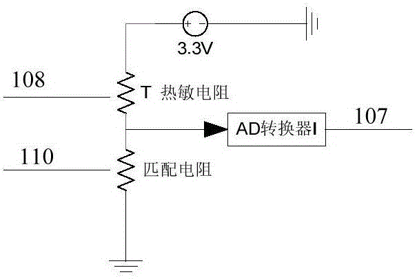
[0024] figure 1 It is a block diagram of a system structure realized according to the present invention. This embodiment consists of an APD array chip 101, a thermistor 108, an AD converter I 107, a matching resistor 110, an AD converter II 105, a microprocessor 102, a digital potentiometer 103, Output adjustable high voltage module 104, buzzer 109 and display module 106 constitute. Thermistor 108 is fixed on the APD array chip 101; AD converter I is connected to thermistor 108 and matching resistor 110; the output end of output adjustable high voltage module 104 is connected to AD converter II 105 and APD array chip 101; output is adjustable The control terminal of the high voltage module 104 is connected with the digital potentiometer 103 ;

[0025] The APD array chip 101 is a 5x5 square APD array chip produced by Germany First sensor company in this embodiment. 25 APD units are integrated on the chip, and these APD units form a 5x5 square array.

[0026] Thermistor 108 is...


PUM


Abstract

The invention discloses a bias voltage full-automatic temperature compensation system for an APD array chip. The bias voltage full-automatic temperature compensation system comprises the APD array chip (101), a thermistor (108), an AD converter I (107), a matching resistor (110), an AD converter II (105), a microprocessor (102), a digital potentiometer (103), an output-adjustable high-voltage module (104), a buzzer (109) and a display module (106). The bias voltage full-automatic temperature compensation system has the advantages that the working temperature of the APD array chip can be obtained by detecting the resistance of the thermistor so as to obtain the needed optimal reverse bias voltage, then the digital potentiometer is used to change the output voltage of the output-adjustable high-voltage module to allow the APD array chip to obtain the reverse bias voltage matched with the current working temperature, and a reverse bias voltage full-automatic temperature compensation function of the APD array chip is achieved.

Description

technical field [0001] The invention relates to an APD bias voltage regulation technology, in particular to an APD array bias high-voltage automatic temperature compensation system. Background technique [0002] When an APD (avalanche photodiode) under reverse high voltage bias is irradiated with light, the current flowing through the APD will produce an avalanche multiplication effect. The closer the APD reverse bias voltage is to the avalanche breakdown voltage, the more significant the avalanche multiplication effect will be, but at the same time, additional noise effects will be generated that will overwhelm the useless signal. Therefore, precise control of the APD reverse bias voltage has become the biggest problem in the practical application of APD. Since the avalanche breakdown voltage changes with temperature, it is necessary to control the APD bias high voltage to also follow the temperature change. [0003] "Optical Communication Technology" Journal 12, 2014 "Des...

Claims


Application Information

Patent Timeline
Patent Type & Authority Applications(China)
IPC IPC(8): G05F1/567
CPCG05F1/567
Inventor 张飙周国清周祥
Owner GUILIN UNIVERSITY OF TECHNOLOGY
Why Eureka
Try Eureka