Adsorption and catalysis integrated device for organic waste gas

A technology for adsorption and catalysis and organic waste gas, which is applied in gas treatment, incinerator, transportation and packaging, etc. It can solve the problems of low treatment efficiency of organic waste gas treatment devices, low removal rate of organic matter, secondary pollution of tail gas, etc., and achieve energy saving effect Significant, fully automated operation process, and stable operation process

Inactive Publication Date: 2016-12-07
霍普科技(天津)股份有限公司
View PDF5 Cites 15 Cited by
  • Summary
  • Abstract
  • Description
  • Claims
  • Application Information

AI Technical Summary

Problems solved by technology

However, due to the different waste gas components and waste gas concentrations in different industries and different enterprises, the removal rate of organic matter in the waste gas by a single treatment method or device is not high, and the treated tail gas still has the problem of secondary pollution, making the organic waste gas The treatment device has low treatment efficiency and poor treatment effect

Method used


Image

  • Adsorption and catalysis integrated device for organic waste gas
  • Adsorption and catalysis integrated device for organic waste gas
  • Adsorption and catalysis integrated device for organic waste gas

Examples


Embodiment 1

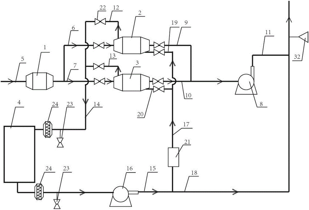
[0040]An organic waste gas adsorption and catalysis integrated device, the device includes a filter device 1, a No. 1 activated carbon adsorption box 2, a No. 2 activated carbon adsorption box 3 and a catalytic combustion bed 4. The waste gas to be treated passes through the waste gas pipeline 5 and enters the filter device 1. The filter device 1 communicates with No. 1 activated carbon adsorption box 2 and No. 2 activated carbon adsorption box 3 through No. 1 exhaust gas inlet pipe 6 and No. 2 exhaust gas inlet pipe 7 respectively. No. 1 activated carbon adsorption box 2 and No. 2 activated carbon adsorption box 3 It communicates with the adsorption main exhaust fan 8 through No. 1 net gas outlet pipe 9 and No. 2 net gas outlet pipe 10 respectively. The adsorption main exhaust fan 8 communicates with the atmosphere through the clean gas pipeline 11. The No. 1 activated carbon adsorption No. 1 desorption intake pipe 12 and No. 2 desorption intake pipe 13 are arranged on box 2 a...

Embodiment 2

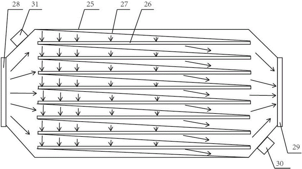
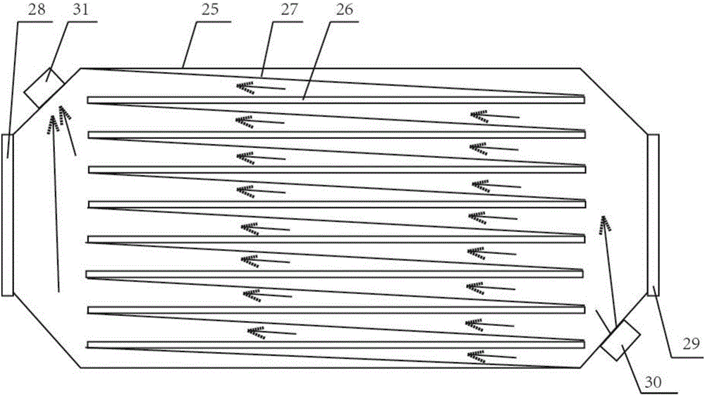
[0045] Others are all the same as in the embodiment, the difference is that the filtering device is a biological trickling filter, and the biological trickling filter is cylindrical, and the inside includes a liquid collection pool 34, a filter material layer 35 and a spray tank arranged in sequence from bottom to top. Shower room 36, spray room 36 is connected with liquid sump 34 through circulation pump 37, and described filter material layer 35 comprises several filter material cylinders 38, and described filter material cylinder 38 is fixed on the biotrickling filter through filter screen 39 In the device, the filter material cylinder 28 is in the shape of a truncated cone, the cross section of the filter material cylinder 28 is circular, and the ratio of the diameter of the upper surface of the filter material cylinder 28 to the diameter of the lower surface is 0.9-0.95:1. A gas drying box 40 is arranged between the filter filter and No. 1 activated carbon adsorption box a...


PUM


Abstract

The invention discloses an adsorption and catalysis integrated device for organic waste gas. The device comprises a filtering unit, a first activated carbon adsorption tank, a second activated carbon adsorption tank and a catalytic combustion bed, wherein to-be-treated waste gas enters the filtering unit through a waste gas pipe, the filtering unit communicates with the first activated carbon adsorption tank and the second activated carbon adsorption tank through a first waste gas inlet pipe and a second waste gas inlet pipe respectively, and a first desorption gas inlet pipe and a second desorption gas inlet pipe are arranged on the first activated carbon adsorption tank and the second activated carbon adsorption tank and communicate with a gas inlet of the catalytic combustion bed through a main desorption gas inlet pipe; a gas outlet of the catalytic combustion bed is connected with a gas outlet channel, and the gas outlet channel communicates with a desorption fan.

Description

technical field [0001] The invention belongs to the field of organic waste gas treatment equipment, in particular to an organic waste gas adsorption and catalysis integrated device. Background technique [0002] Characteristics of organic waste gas treatment: Organic waste gas is generally flammable and explosive, toxic and harmful, insoluble in water, soluble in organic solvents, and difficult to treat. In the treatment of organic waste gas, various principles such as organic waste gas activated carbon adsorption treatment method, catalytic combustion method, catalytic oxidation method, acid-base neutralization method, and plasma method are commonly used. Activated carbon adsorption is to use the porosity of activated carbon to adsorb pollutants. Activated carbon adsorption has a capacity limit, and it is saturated when the adsorption is about 20%, and the activated carbon needs to be replaced. The plasma method is mainly based on high-voltage discharge, which produces dis...

Claims


Application Information

Patent Timeline
Patent Type & Authority Applications(China)
IPC IPC(8): B01D53/04B01D46/24B01D46/12F23G7/07
CPCB01D46/2411B01D53/0407F23G7/07B01D2253/102B01D2259/4009B01D46/121
Inventor 孙浩
Owner 霍普科技(天津)股份有限公司
Why Eureka
Try Eureka