Eureka AIR delivers breakthrough ideas for toughest innovation challenges, trusted by R&D personnel around the world.

Chemical looping combustion device and method based on tower bubbling fluidized bed fuel reactor

A technology of fuel reactor and bubbling fluidized bed, which is applied in the direction of fluidized bed combustion equipment, combustion method, fuel burned in molten state, etc., which can solve the problem of reduced chemical chain combustion efficiency of solid fuel, unfavorable gas-solid contact, and reduced reaction Efficiency and other issues to achieve the effect of improving gas-solid mixing, inhibiting the growth of bubbles, and ensuring combustion efficiency

Active Publication Date: 2016-12-21
SOUTHEAST UNIV
View PDF6 Cites 13 Cited by
  • Summary
  • Abstract
  • Description
  • Claims
  • Application Information

AI Technical Summary

Problems solved by technology

In the fuel reactor, compared with the reduction reaction of the oxygen carrier, the gasification reaction of the solid fuel is very slow, which is a key process to control the combustion rate of the entire chemical chain. It is necessary to take measures to improve the gasification of the fuel in the fuel reactor. residence time to ensure the full reaction of the fuel; otherwise, there will be more fine coke particles that are not completely gasified and will be carried away by the airflow from the fuel reactor, resulting in a decrease in the combustion efficiency of the solid fuel chemical chain
In addition, the existence of bubbles in the conventional bubbling fluidized bed reactor is not conducive to gas-solid contact and reduces the efficiency of the reaction. Effective measures need to be taken to improve the gas-solid flow characteristics in the bubbling fluidized bed

Method used


Image

  • Chemical looping combustion device and method based on tower bubbling fluidized bed fuel reactor
  • Chemical looping combustion device and method based on tower bubbling fluidized bed fuel reactor
  • Chemical looping combustion device and method based on tower bubbling fluidized bed fuel reactor

Examples


Embodiment 1

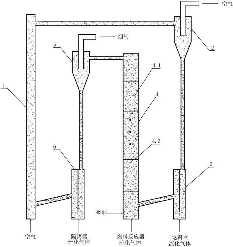
[0036] A method for a chemical chain combustion device based on a tower-type bubbling fluidized bed fuel reactor is that the fuel is not directly contacted and combusted with air, and the fuel is gas fuel. Gas fuels are reducing gases, including CO, H 2 and CH 4 and other gaseous fuels containing hydrocarbons. The gas fuel enters the tower fuel reactor 4, and the oxidation-reduction reaction is alternately cyclically carried out between the air reactor 1 and the tower fuel reactor 4 through the oxygen carrier, so as to realize the combustion of the gas fuel, and the oxygen carrier includes Various oxygen carrier particles such as nickel-based, iron-based, and copper-based; the specific method includes the following steps:

[0037] 1) Oxidation reaction: the fluidizing gas enters the tower fuel reactor 4 through the fuel reactor fluidizing gas inlet at the bottom of the tower fuel reactor 4, and the gaseous fuel enters the tower fuel reactor 4 through the fuel inlet on the bo...

Embodiment 2

[0044] A method for a chemical chain combustion device based on a tower-type bubbling fluidized bed fuel reactor is that the fuel is not directly contacted and combusted with air, and the fuel is a solid fuel. Solid fuels are solid fuels containing hydrocarbons, including coal, biomass, and domestic sludge. The solid fuel enters the tower fuel reactor 4, and the oxidation-reduction reaction is carried out alternately between the air reactor 1 and the tower fuel reactor 4 through the oxygen carrier, so as to realize the combustion of the solid fuel, and the oxygen carrier includes Various oxygen carrier particles such as nickel-based, iron-based, and copper-based; the specific method includes the following steps:

[0045] 1) gasification reaction: the fluidizing gas enters the tower fuel reactor 4 through the fuel reactor fluidizing gas inlet at the bottom of the tower fuel reactor 4, and the solid fuel enters the tower through the fuel inlet on the bottom side of the tower fue...

Embodiment 3

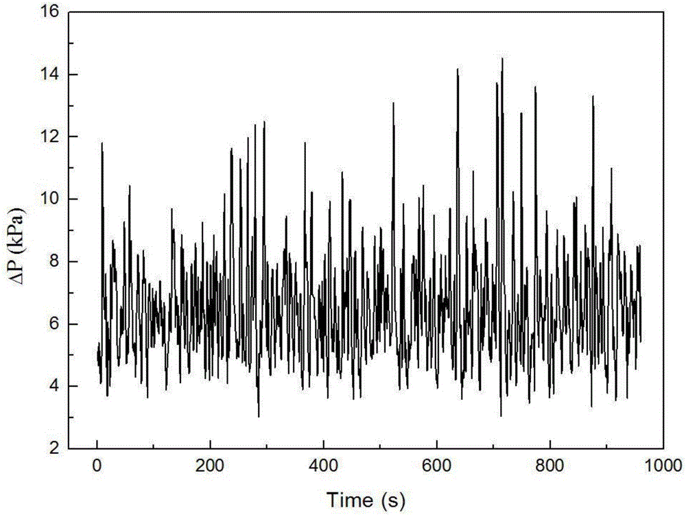
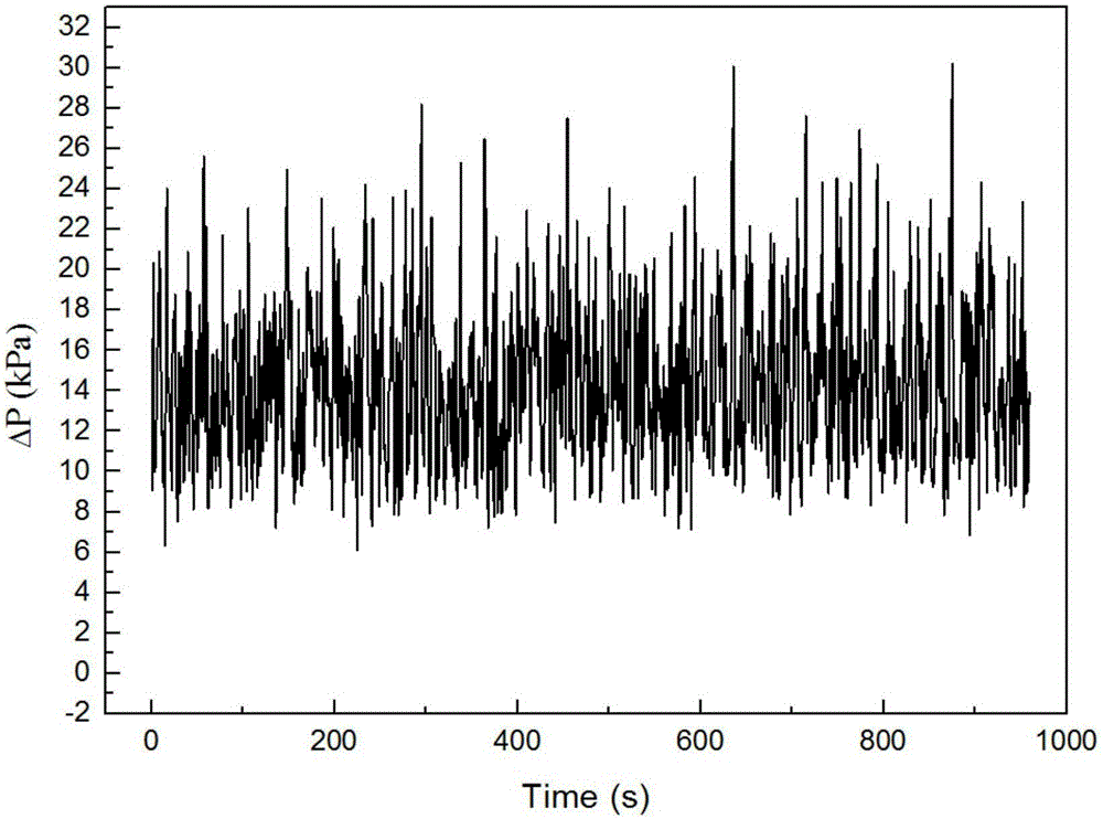
[0055] Quartz sand was used instead of oxygen carrier particles to carry out cold circulation experiments at room temperature. The particle size of quartz sand was 0.1-0.3 mm. Four independent air distribution baffles were set in the tower fuel reactor along the height direction. The fuel reactor is divided into five chambers, through figure 2 , image 3 The pressure drop curve of the bed found that the pressure fluctuated within a certain range with the passage of time, and the mean value was stable around a certain fixed value. This shows that the material circulation in the fluidized bed is in good condition, and the materials in the air reactor and the fuel reactor reach a dynamic balance. And during the circulation process, no obvious plug flow and throttling phenomenon were observed in the tower fuel reactor, the flow was uniform, and the gas-solid mixing was good.

[0056] In summary, the chemical chain combustion device and method based on a tower bubbling fluidized...


PUM

PropertyMeasurementUnit
Particle sizeaaaaaaaaaa

Abstract

The invention provides a chemical looping combustion device and method based on a tower bubbling fluidized bed fuel reactor. The device is a circulating loop composed of an air reactor, an air cyclone separator, a return feeder, the tower fuel reactor, a fuel cyclone separator and an isolator. The method includes the steps that fuel in the tower fuel reactor sequentially upward passes through small chambers divided by multiple independent air distribution partition boards in the height direction to be subjected to deep oxidation reaction with oxidation state oxygen carriers, the mixture is converted into CO2 and H2O to be discharged, reduction state oxygen carriers enter the air reactor through the fuel cyclone separator and the isolator for oxygen carrier regenerative reaction to generate oxidation state oxygen carriers, and the oxidation state oxygen carriers are separated through the air cyclone separator and then enter the fuel reactor through the return feeder; solid fuel is subjected to gasification reaction in the small chamber on the lower portion of the fuel reactor and then is subjected to oxidation reaction. By means of the device and method, the air-solid flow state in the fuel reactor can be effectively improved, and chemical looping combustion efficiency is improved.

Description

technical field [0001] The invention relates to a device and a method for chemical chain combustion of a tower-type bubbling fluidized bed fuel reactor, in particular for improving the gas-solid mixing state in the fuel reactor, suppressing the growth of bubbles, and increasing solid particles in the fuel reaction The device and method of chemical chain combustion for separating carbon dioxide in the combustion process are completed by reducing the residence time of the device, improving the combustion efficiency, and completing the combustion process. Background technique [0002] Chemical chain combustion is a new type of combustion technology. With the help of oxygen carriers, alternate oxidation-reduction reactions are carried out between the air reactor and the fuel reactor to realize the transfer of oxygen, thereby avoiding the direct contact between the fuel and the air, and completing the fuel chemical process. The principle of energy conversion is as follows: the re...

Claims


Application Information

Patent Timeline
IPC IPC(8): F23C10/10F23C10/18F23C10/20
CPCF23C10/10F23C10/18F23C10/20Y02E20/34
Inventor 沈来宏王璐璐沈天绪蒋守席闫景春刘卫东牛欣顾海明
Owner SOUTHEAST UNIV
Why Eureka
Eureka Blog
Learn More