Eureka AIR delivers breakthrough ideas for toughest innovation challenges, trusted by R&D personnel around the world.

High-precision grating positioning device directly driven by a limited angle motor

A technology of limited rotation angle and positioning device, which is applied in the field of testing, can solve the problems of easy wear of stepping motors, compact motors, and limited service life of the system, so as to eliminate transmission errors and transmission losses, reduce development and maintenance costs, The effect of strong practicality and versatility

Inactive Publication Date: 2017-01-25
THE 41ST INST OF CHINA ELECTRONICS TECH GRP
View PDF9 Cites 9 Cited by
  • Summary
  • Abstract
  • Description
  • Claims
  • Application Information

AI Technical Summary

Problems solved by technology

[0005] In this scheme, the combination of stepper motor and harmonic reducer is an indirect drive scheme. In order to meet the accuracy requirements, on the one hand, it is necessary to improve the transmission accuracy of the reducer, and on the other hand, it is necessary to further electronic subdivision to increase the stepping angle of the stepper motor. The higher the resolution, the higher the requirements on the performance of the motor and the reducer, and the corresponding increase in cost. The difficulty of the servo control system increases. At the same time, the stepping motor is easy to wear and is greatly affected by the external environment, and the service life of the system is affected. limitations, and there are problems of mechanical transmission errors and lost steps, this solution is difficult to achieve high-precision grating positioning
[0006] Another method is to use a DC brushless motor and a high-precision photoelectric encoder to form a position closed-loop system for direct drive control. The positioning accuracy mainly depends on the accuracy of the photoelectric encoder. This method can avoid the transmission error and transmission loss of indirect drive. , and has the advantages of fast, strong, no return difference and insensitivity to wear or environmental changes, and is widely used in high-precision positioning systems for rotating mechanisms, but the servo control system of this method is relatively complicated, because the motor needs a Hall sensor to detect the position For commutation, the volume of the motor cannot be very compact, the size and weight are large, and there are prone to position blind spots. At the same time, the high precision requirements greatly increase the resolution requirements for the photoelectric encoder, and the cost is high.

Method used


Image

  • High-precision grating positioning device directly driven by a limited angle motor
  • High-precision grating positioning device directly driven by a limited angle motor
  • High-precision grating positioning device directly driven by a limited angle motor

Examples


Embodiment Construction

[0037] The following will clearly and completely describe the technical solutions in the embodiments of the present invention with reference to the accompanying drawings in the embodiments of the present invention. Obviously, the described embodiments are only some, not all, embodiments of the present invention. Based on the embodiments of the present invention, all other embodiments obtained by persons of ordinary skill in the art without making creative efforts belong to the protection scope of the present invention.

[0038] At present, in order to realize a high-precision grating rotary positioning system, the common method is to use a precision stepping motor, a high-precision harmonic reducer and an angle sensor to form a position open-loop or semi-closed-loop indirect drive control, but this method is difficult to achieve high-precision speed control , The performance requirements of the motor and the angle sensor are high, so the cost of development and maintenance is h...


PUM


Abstract

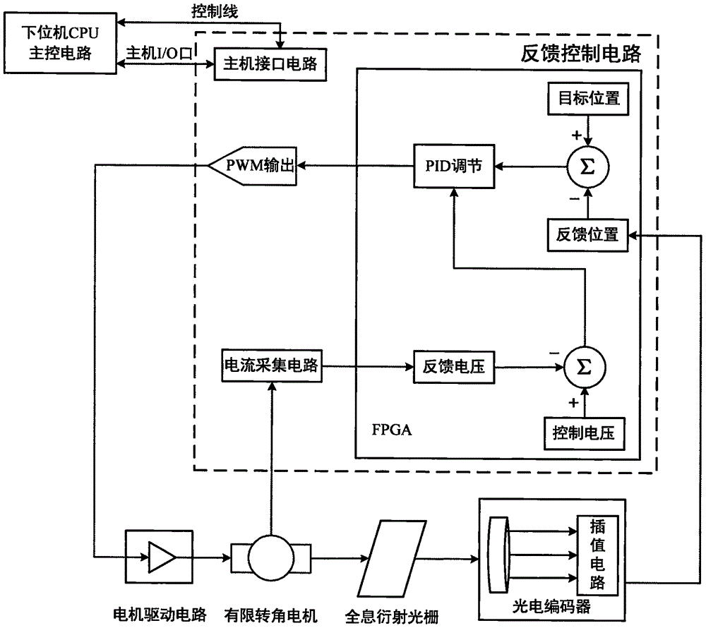
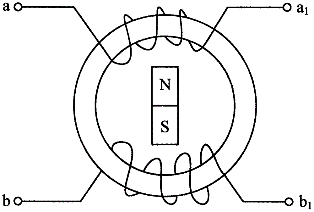
The invention provides a high-precision grating positioning device directly driven by a limited angle motor, which comprises a motor drive circuit, a limited angle motor, a holographic diffraction grating, a photoelectric encoder, an interpolation circuit and a feedback control circuit. The rotor on one side of the limited angle motor passes directly through the bottom of the diffraction grating, while ensuring the center of the grating is located on the shaft, the stator is fixed on the outer heat dissipation frame, the motor is connected with the load through rigid coupling and directly drives the grating to rotate; the photoelectric encoder detects the angular position of the diffraction grating, and the output terminal of the photoelectric encoder is connected with the interpolation circuit. The interpolation circuit amplifies the sine and cosine signals outputted by the photoelectric encoder, doubles the frequency and interpolates after conversion, and connects the feedback control circuit through the interpolated output signal; the feedback control circuit achieves double closed-loop control of current feedback and position feedback, and the motor drives the circuit to generate the drive voltage to control the motor rotation. The high-precision grating positioning device has strong anti-interference ability, high resolution precision, and strong practicability and versatility.

Description

technical field [0001] The invention relates to the technical field of testing, in particular to a grating positioning device and a grating positioning method. Background technique [0002] At present, due to the advantages of large transmission capacity, high transmission rate, anti-electromagnetic interference, and strong confidentiality, optical fiber communication technology has been rapidly developed and widely used in various fields such as military, industry, agriculture, medical treatment, and scientific research. The grating rotating spectrum analyzer is the most common optical frequency domain measurement instrument in the optical fiber communication system, and its wavelength tuning is controlled by the angular position of the diffraction grating of the spectroscopic unit. The incident light beam is collimated by the collimating parabolic mirror and irradiated on the diffraction grating, and different lights diverge along different angles. For each angular positi...

Claims


Application Information

Patent Timeline
Patent Type & Authority Applications(China)
IPC IPC(8): G01J3/28H02P6/00H02P6/30H02K11/22
CPCG01J3/2889G01J2003/2893H02P6/005
Inventor 侯喜报李立功张志辉韩顺利刘磊吴威项国庆李志增
Owner THE 41ST INST OF CHINA ELECTRONICS TECH GRP
Why Eureka
Eureka Blog
Learn More