BOG and oil gas combined recycling system of LNG oil gas cooperative station

A recovery system, oil and gas technology, applied in pipeline systems, gas treatment applications, gas treatment/storage effects, etc., can solve high desorption operating costs and adsorption material investment costs, low oil and gas recovery rate in the condensation section, and insufficient cooling capacity. and other problems, to achieve the effect of reducing the investment of process equipment, reducing the energy consumption of the compression refrigeration system and the amount of refrigerant required, and improving the efficiency of cooling capacity utilization

Active Publication Date: 2017-02-15
CHANGZHOU UNIV
View PDF5 Cites 12 Cited by
  • Summary
  • Abstract
  • Description
  • Claims
  • Application Information

AI Technical Summary

Problems solved by technology

However, this method has high operating costs for condensation, and the recovery rate of oil and gas in the condensation section is far lower than the recovery rate corresponding to the emission standard. It is necessary to set up a large-scale adsorption section. In the long run, it will also bring higher desorption operating costs and adsorption material input costs.
[0011] In addition, oil and gas recovery and BOG recovery are currently divided into separate systems, and there are pro...

Method used


Image

  • BOG and oil gas combined recycling system of LNG oil gas cooperative station
  • BOG and oil gas combined recycling system of LNG oil gas cooperative station

Examples


Embodiment Construction

[0039] The following will clearly and completely describe the technical solutions in the embodiments of the present invention with reference to the accompanying drawings in the embodiments of the present invention. Obviously, the described embodiments are only some, not all, embodiments of the present invention. Based on the embodiments of the present invention, all other embodiments obtained by persons of ordinary skill in the art without creative efforts fall within the protection scope of the present invention.

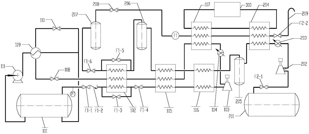
[0040] Such as figure 1 As shown, the device of this embodiment includes LNG storage tank (101), No. 1 heat exchanger (102), No. 2 heat exchanger (105), common compressor (103), BOG water cooler (104), No. 3 Heat exchanger (106), heat exchanger No. 4 (107), BOG No. 1 throttle expansion valve (108), BOG condenser (109), BOG No. 2 throttle expansion valve (110), LNG cryogenic pump (111 ), oil and gas buffer tank (201), oil and gas compressor (202), oil and gas water...


PUM


Abstract

The invention discloses a BOG and oil gas combined recycling system of an LNG oil gas cooperative station. According to the BOG and oil gas combined recycling system, BOG and oil gas are synchronously recycled, in the oil gas recycling process, mixed gas is compressed and subjected to water cooling and is pre-cooled through a refrigerating medium, and then, the mixed gas is sequentially subjected to the common condensation link in which the cooling capacity is provided by the low-temperature BOG and the copious cooling link for oil gas recycling; and the obtained low-temperature oil gas exhausted gas is conveyed into a pre-cooling heat exchanger, and the amount of the refrigerating medium for pre-cooling and the refrigerating energy consumption are reduced. In the BOG recycling process, the low-temperature BOG is heated to the normal temperature after being subjected to heat exchange in the copious cooling link and the common condensation link, the BOG is compressed through an ordinary compressor and then is subjected to water cooling, combined cooling of the low-temperature oil gas exhausted gas and the refrigerating medium, low-temperature BOG cooling, one-time throttling expansion cooling and the super-cooling LNG cooling to be cooled step by step, and finally the LNG is formed through secondary throttling expansion condensation. According to the BOG and oil gas combined recycling system, the BOG cooling capacity is sufficiently utilized for oil gas and BOG recycling, the exhausted gas adsorption link is not needed, a BOG compressor is not needed, the cooling capacity is exchanged step by step, operation is convenient, energy saving and consumption reduction are achieved, safety is high, and equipment investment is small.

Description

technical field [0001] The invention relates to the field of oil and gas and BOG processing in LNG oil and gas joint construction stations, and in particular relates to a new energy-saving process and device for recovering oil and gas and BOG by utilizing the cold capacity of BOG in LNG oil and gas joint construction stations. Background technique [0002] When new LNG filling stations are faced with difficulties such as site selection and urban land shortage, taking advantage of the coverage of existing gas stations and rebuilding oil and gas joint construction stations on the basis of gas stations has become the first choice of many oil and gas sales companies. At present, about 100,000 gas stations across the country are under joint construction. In the LNG oil and gas joint construction station, LNG is stored in low-temperature LNG storage tanks at atmospheric pressure at 0.1MPa and -163°C. During storage and loading and unloading, it will be affected by environmental he...

Claims


Application Information

Patent Timeline
IPC IPC(8): F17C5/02F17C13/00F17C13/04F17D1/02
CPCF17C5/02F17C13/00F17C13/04F17C2221/033F17C2223/0161F17C2227/0341F17C2227/0388F17C2265/034F17C2270/0139F17D1/02
Inventor 吕爱华郭文敏黄维秋
Owner CHANGZHOU UNIV
Why Eureka
Try Eureka