Eureka AIR delivers breakthrough ideas for toughest innovation challenges, trusted by R&D personnel around the world.

Full-automatic purification device for laboratory acid mist exhaust gas

A purification device, fully automatic technology

Inactive Publication Date: 2017-02-22
YANGZHOU UNIV
View PDF7 Cites 6 Cited by
  • Summary
  • Abstract
  • Description
  • Claims
  • Application Information

AI Technical Summary

Problems solved by technology

Although the emissions of the latter are generally small, the sum of them accumulated over a long period of time is also extremely considerable.
Moreover, different from standardized industrial processes, the types and concentrations of pollutants contained in laboratory exhaust gas are often more diverse and unpredictable, and some chemical substances with special toxicity are more likely to be produced, which has extremely serious potential dangers.
The existing domestic gas treatment equipment is aimed at treating the acid gas in the factory's acid treatment vehicle. This acid is acid mist at room temperature, and it is a single acid. Like a laboratory, it uses a small amount of acid to disperse, heat at high temperature, and several types of acid. There are no corresponding treatment facilities for acid-mixed waste gas. Even so, some domestic units have proposed some treatment plans for the characteristics of laboratory acid waste gas.
Due to the complex composition of the experimental waste liquid, it is difficult to achieve the ideal treatment effect by using the traditional treatment process

Method used


Image

  • Full-automatic purification device for laboratory acid mist exhaust gas

Examples


Embodiment Construction

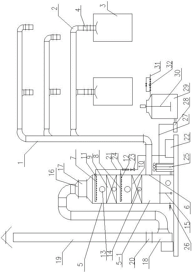
[0020] like figure 1 As shown, the present invention includes a main waste gas collection pipe 1, three waste gas collection branch pipes 2, and the output end of each waste gas collection branch pipe 2 is respectively connected to the waste gas collection main pipe 1; There are two fume hoods 3, and electric regulating air valves 4 are respectively arranged between each fume hood 3 and the exhaust gas collection branch pipe 2; the output end of the exhaust gas collection main pipe 1 is connected to the air inlet 6 at the lower part of the purification tower 5.

[0021] The purification tower 5 includes a shell 5-1, an upper spray pipe 7, a lower spray pipe 8, a first Pall ring packing layer 9, and a second Pall ring packing layer 10; the upper spray pipe 7, the first The Pall ring packing layer 9, the lower spray pipe 8 and the second Pall ring packing layer 10 are sequentially arranged from top to bottom along the height direction of the casing 5-1; A lower spiral nozzle 12...


PUM


Abstract

The invention discloses a full-automatic purification device for laboratory acid mist exhaust gas and relates to the technical field of exhaust gas treatment. The full-automatic purification device comprises an exhaust gas collection main pipeline and a plurality of exhaust gas collection branch pipelines, wherein two draught cupboards are respectively arranged at the input end of each exhaust gas collection branch pipeline, and the output end of the exhaust gas collection main pipeline is connected with an air inlet in the lower portion of a purification tower; the purification tower comprises a shell, an upper spray pipe, a lower spray pipe, a first Pall ring filler layer and a second Pall ring filler layer, an exhaust gas outlet is formed in the upper end of the shell and provided with a demister, the demister is connected with a discharging pipe through a variable-frequency fan, the upper spray pipe and the lower spray pipe are connected with the output end of a circulating water pump respectively through circulating fluid inlet pipes, the input end of the circulating water pump is connected with a circulating water tank, the input end of the circulating water tank is connected with the lower portion of the purification tower, the circulating water tank is connected with the output end of a chemical adding pump through a chemical adding pipe, and the input end of the chemical adding pump is connected with a sodium hydroxide absorption liquid storage tank. The full-automatic purification device is low in energy consumption, high in purification efficiency and wide in applicable range.

Description

technical field [0001] The invention relates to the technical field of waste gas treatment, in particular to the treatment and discharge technology of laboratory acid mist waste gas. Background technique [0002] Laboratory acid mist exhaust gas refers to some highly corrosive mist-like acidic substances. Usually, the acid mist particles distributed in the air are very small, and the particle size does not exceed 10 μm. Compared with fog, the particles are smaller, but the humidity is higher than that of smoke, and it is a pollutant between water mist and smoke. There are two main ways to form acid mist exhaust gas in the laboratory. One is the evaporation of the surface of the acid solution, and the acid molecules enter the air, absorb water and condense to form acid mist droplets. After surfacing, it explodes, bringing the droplets out into the air to form acid mist. [0003] Hydrochloric acid, nitric acid, sulfuric acid and other acids are commonly used in laboratories ...

Claims


Application Information

Patent Timeline
IPC IPC(8): B01D53/78B01D53/68B01D53/48B01D53/64B01D53/52B01D53/58B08B15/02
CPCB01D53/48B01D53/52B01D53/58B01D53/64B01D53/68B01D53/78B08B15/023B01D2251/304B01D2247/10B01D2257/2047B01D2259/124
Inventor 张键何朝龙张强
Owner YANGZHOU UNIV
Why Eureka
Eureka Blog
Learn More