Integrated electric propulsion power system

A power system and electric propulsion technology, which is applied in the power supply system, current collector, photovoltaic power generation and other directions of aerospace vehicles, and can solve the problem of increasing the volume, weight and cost of the spacecraft, increasing the volume and weight of the spacecraft, and low energy conversion efficiency. and other problems, to achieve the effect of reducing track transfer time, reducing redundant configuration, and improving flexibility

Active Publication Date: 2017-02-22
SHENZHEN ACAD OF AEROSPACE TECH +1
View PDF5 Cites 14 Cited by
  • Summary
  • Abstract
  • Description
  • Claims
  • Application Information

AI Technical Summary

Problems solved by technology

The solar array needs to meet the energy supply requirements of the entire life cycle of the spacecraft platform, and its design should consider the impact of output power reduction caused by failure, aging, etc., so the solar array battery needs to be redundantly configured, and the power of the primary power bus PCU needs to be The power of the electric propulsion power supply PPU is configured redundantly, so the two-level redundant configuration greatly increases the configuration redundancy of the solar array battery, thereby increasing the volume, weight and cost of the spacecraft
[0006] c) The energy conversion efficiency is low, and the overall heat consumption of the spacecraft platform is large
The energy from solar energy to the electric propulsion engine undergoes two-stage power conversion, which leads to low overall efficiency of the spacecraft platform, and requires a large volume and weight of thermal control equipment, which in turn increases the volume and weight of the entire spacecraft.

Method used


Image

  • Integrated electric propulsion power system
  • Integrated electric propulsion power system
  • Integrated electric propulsion power system

Examples


Embodiment Construction

[0026] The present invention will be further described below in conjunction with the accompanying drawings and specific embodiments.

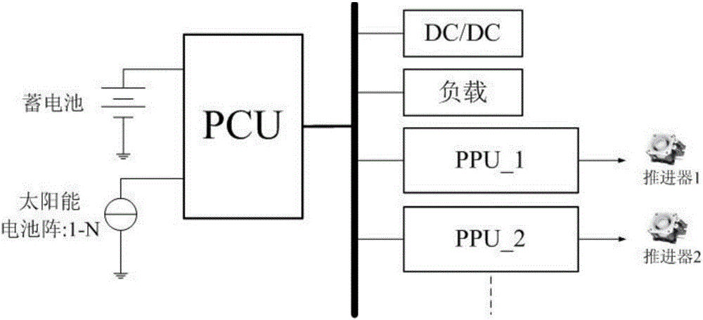
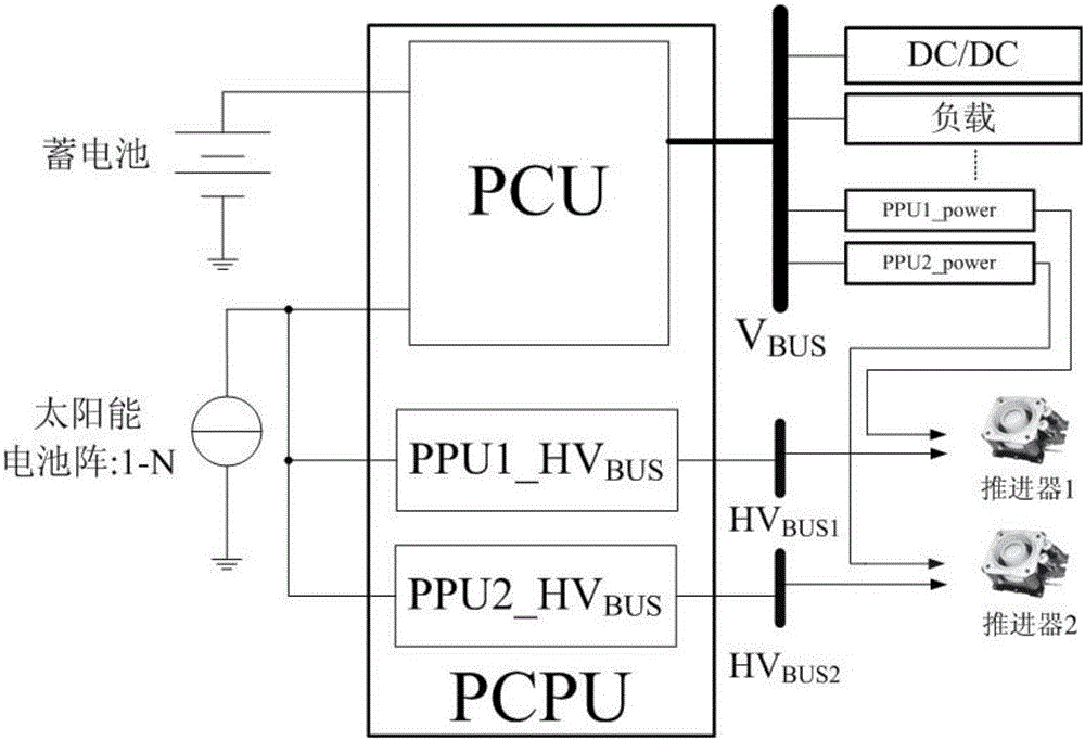
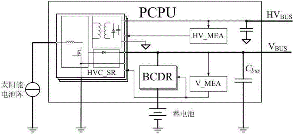
[0027] attached figure 1 What is shown is the centralized power supply and distribution architecture of the traditional high-power all-electric propulsion spacecraft platform. Aiming at the problems of using centralized power supply and timing for this architecture, the present invention proposes a design concept by changing the primary power bus architecture and coupling the PPU high-voltage power supply. a kind of attached figure 2 The brand-new power supply and distribution architecture suitable for high-power all-electric propulsion spacecraft platforms shown in Fig. 1 is the PCPU (power conditioning and processing unit) architecture.

[0028] The anode power supply in the high-power Hall-type all-electric propulsion and the grid power supply in the ion-type all-electric propulsion account for more than 90% of the power required by the en...


PUM


Abstract

The invention provides an integrated electric propulsion power system applied to a high-power integrated electric propulsion spacecraft platform. A novel power supply and distribution architecture and a power regulation and processing unit (PCPU) based on the architecture are designed by changing a primary powder bus architecture and coupling a high-voltage power supply of a PPU. The PPU comprises a high-voltage transformation and shunt regulating HVC_SR module, a BCDR module, a primary power bus error amplifier V_MEA, a high-voltage bus error amplifier HV_MEA, a primary power bus VBUS and a high-voltage bus HVBUS. A high-voltage bus directly takes power from a solar array, the HVC_SR is controlled through the HV_MEA, the energy of the solar array is isolated and boosted to a secondary side, and then the isolated secondary sides of a HVC_SR module set are connected in series and parallel to form the HVBUS so as to meet the demands of different types of electric propulsion systems for the electrical characteristics and quantity of high-voltage buses. The integrated electric propulsion power system can provide more engine domains for an electric propulsion engine and can significantly shorten orbital transfer time, and power transformation and energy scheduling can meet the energy supply and use requirements of an integrated electric propulsion platform better.

Description

technical field [0001] The invention belongs to the technical field of spacecraft power supply, and in particular relates to an all-electric propulsion power system. Background technique [0002] Due to its high specific impulse and high precision of thrust control, space all-electric propulsion technology can significantly increase the payload factor, reduce launch costs, and increase on-orbit life. In some fields, it is increasingly replacing traditional chemical propulsion systems as a space spacecraft propulsion platform. mainstream configuration. Ion electric propulsion and Hall electric propulsion are currently the most mature and widely used electric propulsion products. As the main propulsion system configuration, they are applied to high-power spacecraft platforms, especially high-power synchronous orbit communication satellites, which bring significant costs. and performance advantages, currently it is mainly responsible for the orbit improvement of spacecraft and...

Claims


Application Information

Patent Timeline
Patent Type & Authority Applications(China)
IPC IPC(8): B64G1/42H02S40/30H02J7/00
CPCB64G1/425B64G1/443H02J7/00H02S40/30Y02E10/50
Inventor 付明
Owner SHENZHEN ACAD OF AEROSPACE TECH
Why Eureka
Try Eureka