
Phase change vacuum electric heating furnace

An electric heating furnace and electric heater technology, applied in lighting and heating equipment, furnaces, crucible furnaces, etc., can solve the problems of the reduction of condensation heat transfer coefficient, the reduction of heating efficiency of the heating furnace, and the reduction of the heat transfer coefficient outside the switch, and achieve maintenance Easy maintenance, simple and reliable structure, wide application range

Inactive Publication Date: 2017-02-22
ANBANG ELECTRICAL GRP
View PDF6 Cites 1 Cited by
  • Summary
  • Abstract
  • Description
  • Claims
  • Application Information

AI Technical Summary

Problems solved by technology

[0003] At present, oil-fired, coal-fired, and gas-fired water jacket furnaces are widely used. Some single wells are directly heated by electric furnaces. The core heating elements of these heating methods are heating coils composed of resistance wires and insulating powder. Crude oil or oil-gas mixture flows directly. The furnace body is heated by the heating coil to raise the temperature and lower the viscosity. Due to the high temperature of the heating coil, it is easy to coke the crude oil, and the coking outside the heating coil is getting thicker and thicker, and the heat transfer efficiency is getting lower and lower, which finally leads to an increase in the furnace volume. smaller and even clogged
There are also oil-fired, coal-fired, and gas-fired vacuum heating furnaces. At present, there are two methods for establishing the pure gas phase space of vacuum heating furnaces used in oil fields: the "gas-driven gas" method and the vacuum pump suction method. The "gas-driven gas" method is in After the liquid injection is completed, the top of the heating furnace body is connected to the atmosphere. At this time, the combustion device is started to gasify the carrier during the heating process, so that the non-condensable gas in the furnace body can be eliminated by the carrying effect of the generated gas phase heat carrier ( Air), when exhausted to a certain extent, close the top of the furnace body and isolate it from the atmosphere to form a closed gas phase and liquid phase space; while the vacuum pump suction method is to close the furnace body and isolate it from the atmosphere after the liquid injection is completed, and then Use a vacuum pump to extract the non-condensable gas (air) in the furnace, and when it is drawn to a certain extent, start the combustion device, so that the heat carrier can be gasified during the heating process, forming a closed gas phase and liquid phase space; but using these two methods It is difficult to achieve a higher purity gas phase heat carrier space, the steam still contains a large amount of non-condensable gas (air), if the gas phase space contains 1% non-condensable gas (air), the heat transfer coefficient outside the heating coil will be reduced by 60%, and the condensation heat transfer coefficient will be significantly reduced, resulting in a reduction in the overall heating efficiency of the furnace
In addition, the limitations of oil, coal, gas water jacket furnaces and vacuum furnaces are that the pipe from the wellhead to the heating furnace cannot be heated, it is easy to block, and the heating power is not easy to control, resulting in frequent start and stop, loud noise, The water jacket furnace has low efficiency, and the installation location is far away from the wellhead of the oil well, so there are certain limitations in use

Method used


Image

  • Phase change vacuum electric heating furnace

Examples


Embodiment Construction

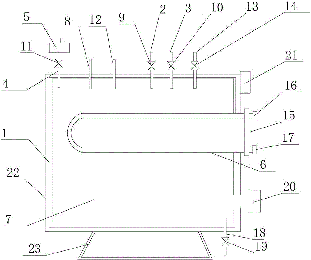
[0023] refer to figure 1 , the present invention proposes a phase-change vacuum electric heating furnace, including a furnace body 1, a liquid injection pipe 2, an exhaust pipe 3, a liquid catheter 4, a liquid discharge pipe 13, an expansion tank 5, a heating coil 6, an electric heater 7. The first explosion-proof junction box 20, the second explosion-proof junction box 21, the pressure sensor 8, the temperature sensor 12, the first liquid level sensor, the second liquid level sensor, and the controller, wherein:

[0024] The top of the furnace body 1 is provided with a liquid injection port, an exhaust port, a first liquid outlet, and a second liquid outlet. The liquid injection pipe 2 is connected to the liquid injection port and the liquid injection pipe 2 is provided with a liquid injection valve 9. The pipe 3 is connected to the exhaust port and the exhaust pipe 3 is provided with a vent valve 10 , the liquid discharge pipe 13 is connected to the second liquid outlet, and...


PUM


Abstract

The invention discloses a phase change vacuum electric heating furnace which comprises a furnace body, a liquid injection tube, a first exhaust tube, a second exhaust tube, a liquid guide tube, an expansion water tank, a heating coil, an electric heater, a pressure sensor, a first liquid level sensor, a second liquid level sensor and a controller; the expansion water tank has the action of overflowing excess water and also supplies micro-positive pressure for the interior of the furnace body to ensure the quantity of non-condensable gas to be zero; a liquid level control valve controls a liquid level in the furnace body; a gas release valve exhausts the non-condensable gas; a liquid injection valve injects water into the furnace body; the electric heater heats liquid at the lower part in the heating furnace body to enable the liquid to evaporate; evaporated liquid condenses into liquid to fall back into the liquid at the lower part in the heating furnace body again after heating the heating coil at the upper part in the furnace body; and the controller is connected with the electric heater, the pressure sensor, the first liquid level sensor, the second liquid level sensor, the liquid injection valve, the gas release valve and the liquid level control valve and controls the electric heater, the pressure sensor, the first liquid level sensor, the second liquid level sensor, the liquid injection valve, the gas release valve and the liquid level control valve to act. The phase change vacuum electric heating furnace is simple and reliable in structure, liable to operate, convenient to maintain, long in service life, high in efficiency and wide in application range.

Description

technical field [0001] The invention relates to the technical field of electric heating furnaces, in particular to a phase-change vacuum electric heating furnace. Background technique [0002] In the existing oil and natural gas extraction and transportation process in oil fields, some self-flowing wells with high pour point oil, high viscous oil, high waxy crude oil and hydrate serious need to be heated for normal production and transportation. [0003] At present, oil-fired, coal-fired, and gas-fired water jacket furnaces are widely used. Some single wells are directly heated by electric furnaces. The core heating elements of these heating methods are heating coils composed of resistance wires and insulating powder. Crude oil or oil-gas mixture flows directly. The furnace body is heated by the heating coil to raise the temperature and lower the viscosity. Due to the high temperature of the heating coil, it is easy to coke the crude oil, and the coking outside the heating c...

Claims


Application Information

Patent Timeline
IPC IPC(8): F27B14/04F27B14/06F27B14/14F27B14/20
CPCF27B14/04F27B14/06F27B14/14F27B14/20F27B2014/045
Inventor 陈更芬李贻连卜基峰
Owner ANBANG ELECTRICAL GRP
Learn More