Device for preparing polishing glue

A technology for preparing equipment and polishing glue, which is applied in the field of auxiliary equipment for optical element processing and polishing material preparation equipment, can solve problems such as uneven distribution of temperature field and polishing glue properties, affecting the surface quality of optical elements, and composition changes The effect of shortening the convergence time of the surface shape, facilitating the control of the surface shape, and reducing the probability of defects

Pending Publication Date: 2017-03-08
成都精密光学工程研究中心
View PDF9 Cites 3 Cited by
  • Summary
  • Abstract
  • Description
  • Claims
  • Application Information

AI Technical Summary

Problems solved by technology

[0004] The traditional polishing glue preparation method is to obtain molten asphalt by heating with an electric furnace. Since there is no real-time monitoring of temperature control, constant temperature and heat preservation functions, the temperature of the asphalt is not controlled and the distribution is extremely uneven during the entire polishing glue preparation process. , causing some asphalt to produce a large amount of volatile matter due to high temperature, and the corresponding composition also changes; mor

Method used


Image

  • Device for preparing polishing glue
  • Device for preparing polishing glue
  • Device for preparing polishing glue

Examples


Embodiment Construction

[0019] Below in conjunction with embodiment the present invention is further described.

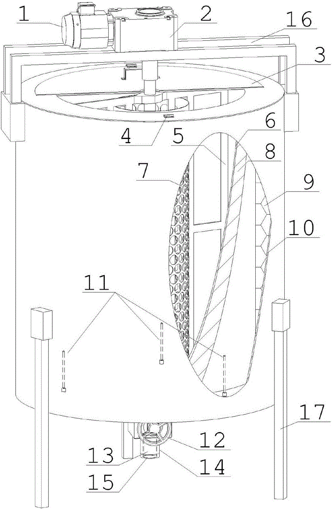
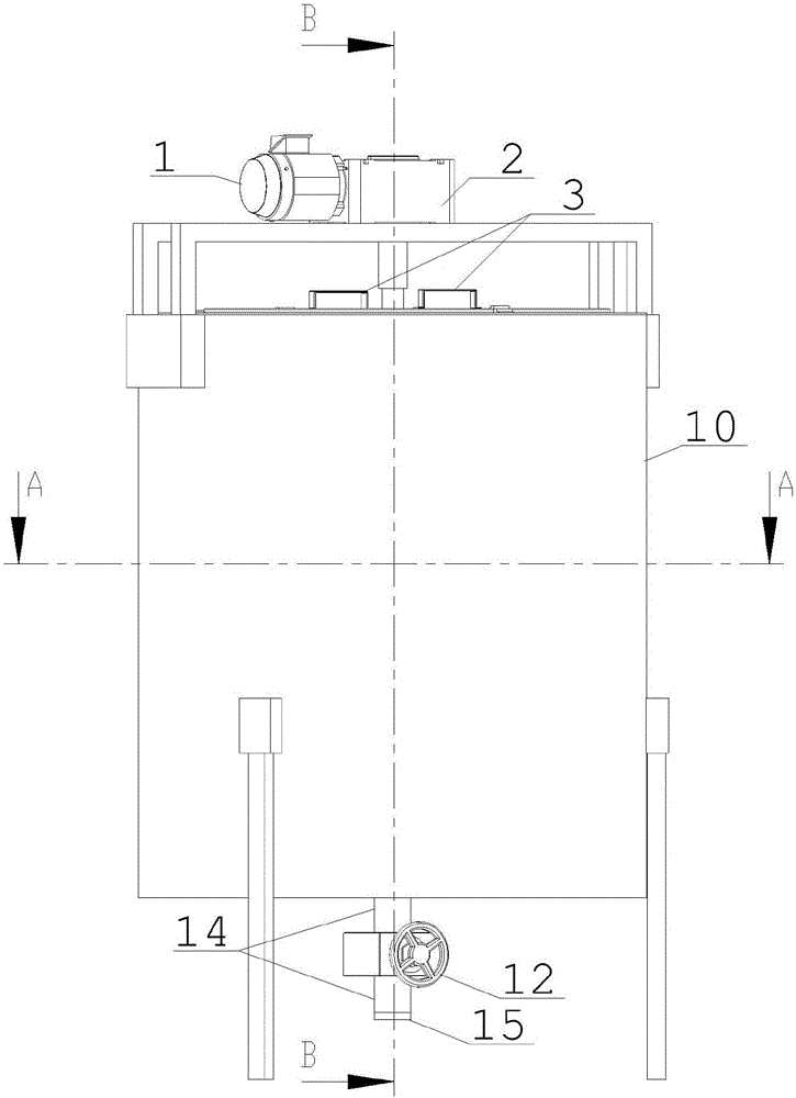
[0020] see figure 1 —5, polishing glue preparation device, comprise the bung and the upper bung 3 that are made up of bung shell 10, bucket inner layer 6 and the insulating layer 9 between the two, bung top is provided with upper bracket 16, upper bracket 16 A motor 1, a reducer 2 and a stirring paddle 5 are installed on the top of the barrel body. There is an annular filter screen 7; an annular ceramic heater 8 is arranged between the barrel inner wall 6 and the insulation layer 9.

[0021] The barrel inner layer 6 is provided with temperature sensors 11 at intervals, and is connected with the heating controller in the control box (not shown in the figure). Through real-time detection and feedback control of the heating controller, the temperature in the barrel is kept stable.

[0022] The outer wall of the discharge pipe 13 is wrapped with thermal insulation cotton 14 .

[0023] The...


PUM


Abstract

The invention discloses a device for preparing polishing glue, belonging to the technical field of optical machining. The device comprises a barrel body, a barrel inner layer, a heat insulation layer between the barrel body and the barrel inner layer, and a barrel cover at the upper part of the device, wherein an upper bracket is arranged at the upper part of the barrel body; a motor, a speed reducer and stirring blades are arranged on the upper bracket; supporting legs are arranged at the lower part of the barrel body; a discharge pipe and a discharge valve are arranged at the bottom of the barrel body; an annular filter net is arranged among the stirring blades in the barrel body; and an annular ceramic heater is arranged between the barrel inner wall and the heat insulation layer. The stress distribution in the polishing glue obtained by pouring forming is uniform, so as to beneficial for controlling the surface shape of a processed element, and shortening the convergence time of the surface shape; however, filter nets arranged in the barrel and at an outlet can filter out impurity particles in a raw material, thereby reducing the content of large-grained impurities on the surface of the formed polishing glue, and reducing the probability of generating defects by an optical element. Finally, automatic production of the polishing glue is achieved, the preparation flow is simplified, and the forming quality of the polishing glue is improved.

Description

[0001] Technical field [0002] The invention relates to auxiliary equipment for processing optical elements, in particular to a preparation device for polishing materials, and belongs to the technical field of optical processing. Background technique [0003] At present, the polishing glue prepared by asphalt is mainly used as the polishing mold in the polishing stage of large-diameter and high-precision optical components. As the asphalt has certain plastic deformation ability and thermal flow characteristics, it can automatically adjust the surface shape and grinding according to the pressure and contact state. Therefore, it can accelerate the speed of surface shape convergence, slow down the scratch damage caused by larger abrasive particles on the machined surface, and finally achieve the purpose of improving surface quality and reducing the thickness of surface metamorphic layer and surface roughness. Based on the above advantages, asphalt polishing glue is widely used a...

Claims


Application Information

Patent Timeline
IPC IPC(8): B01F15/06B01F15/00B01F7/18B01J6/00C10C1/19
CPCB01J6/005C10C1/19B01F27/90B01F35/30B01F35/33B01F35/181B01F35/90B01F35/92B01F2035/99
Inventor 赵恒蔡超王刚马平鄢定尧谢磊何祥朱衡鲍振军
Owner 成都精密光学工程研究中心
Why Eureka
Try Eureka