An electrolytic bath reaction chamber used for in-situ XRD tests and a testing method

A technology of reaction chamber and electrolytic cell, which is applied in the field of electrochemistry, can solve the problems of cumbersome assembly process, low signal-to-noise ratio of the spectrum, uneven current density, etc., and achieve the effects of simple preparation method, accurate test potential and uniform current density

Active Publication Date: 2017-05-10
BTR NEW MATERIAL GRP CO LTD
View PDF3 Cites 11 Cited by
  • Summary
  • Abstract
  • Description
  • Claims
  • Application Information

AI Technical Summary

Problems solved by technology

However, this method has the following defects: 1. There are obvious amorphous peaks of the conductive film, and the signal-to-noise ratio is low; 2. The conductivity of the conductive film is low, which is not conducive to high-rate charge and discharge
This method has the following defects: 1. After the test window is bonded, it is difficult to remove and cannot be reused; 2. Due to the shielding effect of the copper mesh, the signal-to-noise ratio of the obtained spectrum is low, and there are obvious copper characteristic peaks; 3. The electrode (copper mesh) lacks positioning measures, and the working electrode is easy to deviate from the focal plane during XRD testing, resulting in off-axis errors
However,

Method used


Image

  • An electrolytic bath reaction chamber used for in-situ XRD tests and a testing method
  • An electrolytic bath reaction chamber used for in-situ XRD tests and a testing method
  • An electrolytic bath reaction chamber used for in-situ XRD tests and a testing method

Examples


Embodiment 1

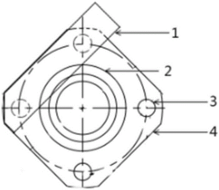
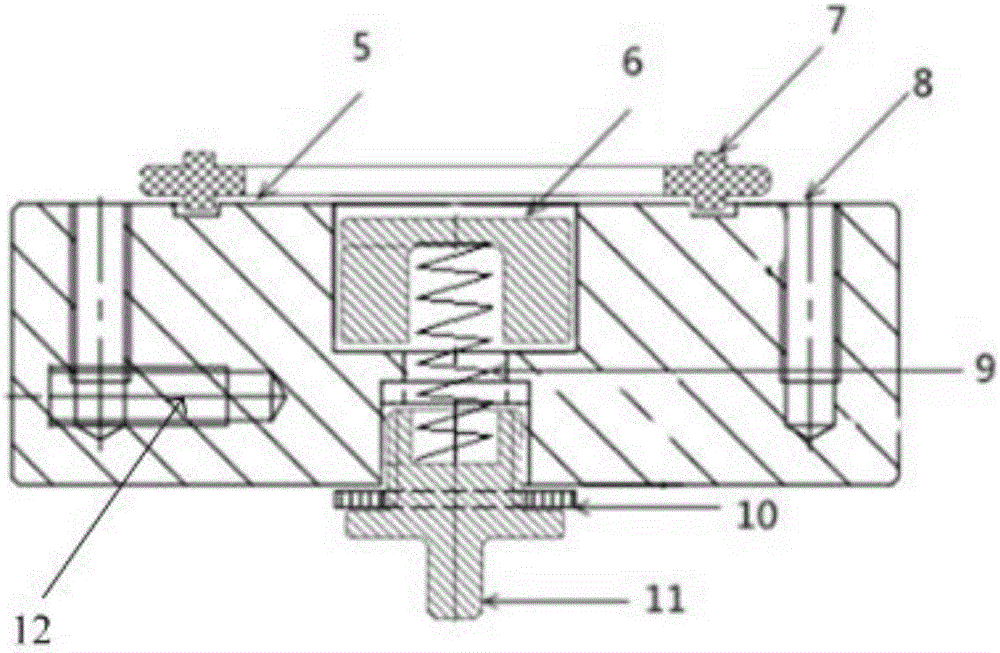
[0070] A kind of electrolytic cell reaction chamber (such as Figure 4 shown), the reaction chamber of the electrolytic cell includes the working electrode cover from top to bottom (such as Figure 1a and Figure 1b shown), the opposite electrode holder (such as figure 2 shown) and the base to fix the counter electrode holder (such as image 3 shown);

[0071] The working electrode cover includes a cover body 4, a test window 2 and a first copper sheet 1. The cover body 4 is provided with a test hole; the test window 2 completely covers the test hole, and the test window 2 is connected to the test hole by welding, bonding or pressing. Sealed connection; the test window 2 is sealed and connected to the test hole, the first copper sheet 1 is connected to the test window 2 by lamination or welding, and is located outside the test hole area; the material of the test window 2 is high X-ray transmission High-rate conductive material, and its characteristic peaks do not overlap o...

Embodiment 2

[0087] Utilize the electrolytic cell reaction chamber described in embodiment 1 to carry out the in-situ XRD test, wherein, the test window 2 is sealed and connected with the test hole by welding, and the test window 2 is a beryllium sheet; the first copper sheet 1 is laminated with the test hole. The test window 2 is connected, and the thickness of the test window 2 is 0.5 mm; there are four first connecting holes 3, second connecting holes 8 and bolts 13; the height of the reaction chamber of the electrolytic cell is 3.0 cm.

[0088] Described test method comprises the steps:

[0089] Step 1) Blend the graphite negative electrode material and binder to make a slurry, apply it directly on the inner side of the test window of the beryllium sheet, wipe off the part exceeding the area of ​​the electrode sheet of the counter electrode, and dry it at 60°C for later use;

[0090] Step 2) In the glove box (argon atmosphere), assemble the counter electrode seat, the sealing screw 11 ...

Embodiment 3

[0097] Utilize the electrolytic cell reaction chamber described in embodiment 1 to carry out the in-situ XRD test, wherein, the test window 2 is sealed and connected with the test hole by bonding, and the test window 2 is a beryllium sheet; the first copper sheet 1 is connected with the test hole by welding. The test window 2 is connected, and the thickness of the test window 2 is 0.05 mm; there are four first connecting holes 3, second connecting holes 8 and bolts 13; the height of the reaction chamber of the electrolytic cell is 1.0 cm.

[0098] Described test method comprises the steps:

[0099] Step 1) Blend the NCA positive electrode material and binder to make a slurry, coat it on the aluminum foil, dry it, roll it, punch it into a circular pole piece according to the size of the counter electrode, and stick it on the inner side of the test window 2, spare;

[0100] Step 2) In the glove box (argon atmosphere), assemble the counter electrode seat, the sealing screw 11 ma...


PUM

PropertyMeasurementUnit
Thicknessaaaaaaaaaa
Heightaaaaaaaaaa
Thicknessaaaaaaaaaa

Abstract

An electrolytic bath reaction chamber used for in-situ XRD tests and a testing method are provided. The electrolytic bath reaction chamber includes a working electrode cover, a counter electrode base and an optional pedestal fixing the counter electrode base in order from top to bottom. The working electrode cover and the counter electrode base are sealed and connected in an insulating manner. The working electrode cover includes a cover body, a testing window and an optional first electric conductor. The counter electrode base includes a base body, a sliding block, a mobile device and an optional second electric conductor. The mobile device is connected to the sliding block and is used for moving the sliding block to allow the sliding block to be adjacent to the testing window. The electrolytic bath reaction chamber when being used for in-situ XRD tests has advantages of a simple and rapid working electrode preparing method, capability of continuous testing on one electrode sheet, few components, convenient assembling, a compact structure, a small size, good equipment universality and capability of being repeatedly used, and has characteristics of a high signal-to-noise ratio, a small off-axis error and no impurity-phase peak interference of obtained spectrums, uniform electric current density of the working electrode, accurate potential testing, high capacity retention rates in long circulation, and the like.

Description

technical field [0001] The invention belongs to the technical field of electrochemistry, and relates to an electrolytic cell reaction chamber and its application, in particular to an electrolytic cell reaction chamber for in-situ XRD testing and a testing method. Background technique [0002] In recent years, with the continuous deepening of research on lithium-ion batteries, new materials and systems such as ternary, NCA, hard carbon, silicon oxide, silicon-based, lithium negative electrodes and other new materials and systems for lithium-ion batteries continue to emerge. During the charging and discharging process of lithium-ion batteries, the phase and lattice parameters of the positive and negative electrode materials will change due to the intercalation, extraction and lithium deposition of lithium ions. Performances such as cycle, magnification, and pole piece expansion are of great significance. [0003] Traditional lithium battery materials study the crystal structu...

Claims


Application Information

Patent Timeline
IPC IPC(8): G01N23/207
CPCG01N23/207G01N2223/056
Inventor 苗恒刘兴杨周成坤周海辉
Owner BTR NEW MATERIAL GRP CO LTD
Why Eureka
Try Eureka