Method for producing sponge iron by reducing pyrites through coal synthesis gas in shaft furnace

A coal-to-synthesis gas and pyrite technology, applied in shaft furnaces, furnaces, furnace types, etc., can solve the problems of low pyrite quality, low pyrite extraction rate, immature equipment, etc., and achieve large gas The effect of utilization rate, large industrial application value, and convenient operation

Inactive Publication Date: 2017-05-31
LUTIAN CHEM CORP
View PDF3 Cites 2 Cited by
  • Summary
  • Abstract
  • Description
  • Claims
  • Application Information

AI Technical Summary

Problems solved by technology

[0003] In view of the above-mentioned shortcomings, the object of the present invention is to provide a method for reducing pyrite in a coal-to-synthesis gas shaft furnace to produce sponge iron, which can not only overcome the low extraction rate of existing pyrite, but also It can solve the problems of low equipment efficiency, immature equipment, poor environmental performance and low quality of pyrite in pyrite roasting and smelting. This method not only uses the abundant pyrite in my country as raw material, but also utilizes the shaft furnace efficient

Method used


Image

  • Method for producing sponge iron by reducing pyrites through coal synthesis gas in shaft furnace

Examples


Embodiment 1

[0026] Preparation of sponge iron:

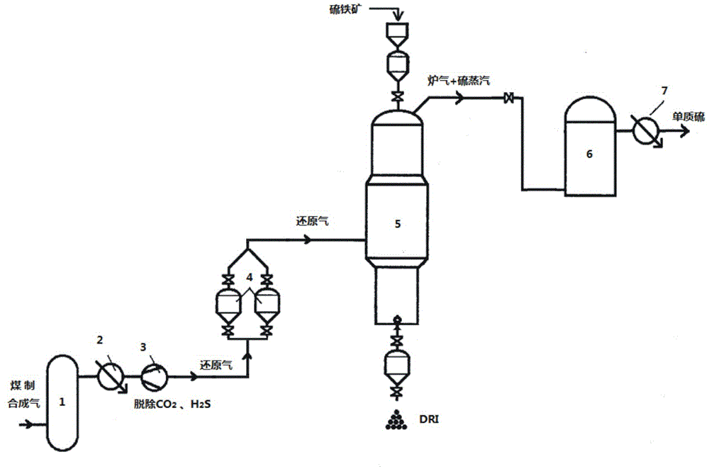
[0027] combine figure 1 As shown, the coal-to-synthesis gas is passed through the water-gas shift device 1 to convert H 2 After adjusting the ratio with CO to 1.73 (volume ratio), it enters the NHD gas purification equipment 2 to remove acid gas components: hydrogen sulfide and carbon dioxide, and obtain a high-pressure reducing gas with a total content of carbon monoxide and hydrogen of 95.7% (volume ratio). After reducing the pressure of the reducing gas to 0.7MPa, it is transported to the heating furnace 4 through the steam turbine 3, and after being heated to 927°C, the reducing gas and pyrite with a sulfur content of 27.8% and iron content of 43.6 are respectively input into the shaft furnace 5. In the moving bed of the furnace, the reducing gas reduces the pyrite to sponge iron, and the sulfur steam and the furnace gas pass through the dedusting cooler 6 to remove the mineral dust, and after cooling down to 400°C, the sulfur is conde...

Embodiment 2

[0029] combine figure 1 As shown, the coal-to-synthesis gas is passed through the water-gas shift device 1 to convert H 2 Adjust the ratio with CO to 2.15 (volume ratio) and enter NHD gas purification equipment 2 to remove acid gas components: hydrogen sulfide and carbon dioxide, and obtain high-pressure reducing gas with carbon monoxide and hydrogen content of 96.1% (volume ratio). After reducing the pressure of the reducing gas to 0.65MPa, it is transported to the heating furnace 4 through the steam turbine 3, and after being heated to 950°C, the reducing gas and pyrite with a sulfur content of 31.2% and iron content of 40.8 are respectively input into the shaft furnace 5. In the moving bed of the furnace, the reducing gas reduces the pyrite to sponge iron, and the sulfur steam and the furnace gas pass through the dedusting cooler 6 to remove the mineral dust, and after cooling down to 400°C, the sulfur is condensed and recovered through the water film desulfurization and de...


PUM

PropertyMeasurementUnit
particle sizeaaaaaaaaaa

Abstract

The invention discloses a method for producing sponge iron by reducing pyrites through coal synthesis gas in a shaft furnace. Hydrogen sulfide and carbon dioxide in the coal synthesis gas are removed through a gas purification process, reducing gas with carbonic oxide and hydrogen as main compositions is obtained, then heated to a preset temperature and introduced into the shaft furnace, the pyrites are reduced into the sponge iron through the reducing gas in the shaft furnace, and obtained sulfur vapor is recovered after being dedusted and condensed. According to the process, the heat furnace is adopted for directly heating the reducing gas, the influence of carbonic oxide carbon precipitation is avoided, the temperature of the reducing gas can be increased to 850-1000 DEG C, briquettes comprising the pyrites are used as raw materials of the shaft furnace, and the cost of the raw materials is lowered.

Description

technical field [0001] The invention relates to a process method for producing sponge iron by reducing pyrite ore in a coal-to-synthesis gas shaft furnace, and belongs to the technical field of direct iron reduction by synthesis gas. Background technique [0002] At present, the method of ironmaking is mainly to use iron ore with sulfur content ≤ 0.5% as raw material for blast furnace ironmaking. my country's iron ore reserves are relatively low, and most of them are imported from abroad. As the price of iron ore in the international market has risen year by year in recent years, it has brought great pressure to my country's iron and steel enterprises and downstream companies of all sizes. . my country is rich in pyrite resources, accounting for 10% of the world's total reserves. Among them, the pyrite reserves in Guxu, Sichuan in western my country and the adjacent Guizhou area account for 8.5% of my country's total pyrite reserves, ranking sixth in the country. Usually, t...

Claims


Application Information

Patent Timeline
Patent Type & Authority Applications(China)
IPC IPC(8): C21B13/02
CPCC21B13/02C21B13/0073
Inventor 蒋弟勇龙平谭光军宁忠培辜凯德刘孔满
Owner LUTIAN CHEM CORP
Why Eureka
Try Eureka