Organic metal iridium complex and organic light-emitting device application thereof

An organic light-emitting device, organometallic technology, applied in the direction of indium organic compounds, platinum group organic compounds, electric solid devices, etc., can solve the problems of lowering the sublimation temperature and failing to meet the requirements of OLED preparation

Inactive Publication Date: 2017-06-13
GUANMAT OPTOELECTRONICS MATERIALS INC
View PDF5 Cites 20 Cited by
  • Summary
  • Abstract
  • Description
  • Claims
  • Application Information

AI Technical Summary

Problems solved by technology

[0021] Although the above-mentioned chelating auxiliary ligands with smaller molecular weights or smaller conjugated chr

Method used


Image

  • Organic metal iridium complex and organic light-emitting device application thereof
  • Organic metal iridium complex and organic light-emitting device application thereof
  • Organic metal iridium complex and organic light-emitting device application thereof

Examples


Embodiment 1

[0093] Example 1: Synthesis of G-2 and G-3 luminescent organometallic iridium complexes

[0094]

[0095] According to the principle shown in the chemical reaction formula I-III, and the above synthetic chemical steps, without departing from the scope of the present invention, the following organometallic iridium compounds were synthesized, and the specific listed complexes were verified by mass spectrometry. For details, see Table 4 below:

[0096] Table 4 Example organometallic iridium complex luminescent material chemical structure and characterization

[0097]

[0098]

[0099]

[0100]

[0101]

[0102]

[0103]

[0104]

Embodiment 2

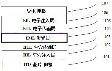
[0105] Example 2 Application example of evaporated OLED device:

[0106] Evaporated OLED devices made: in a background vacuum up to 10 -5 Pa's multi-source evaporation OLED preparation equipment adopts the following device mechanism: Luminescent dopant

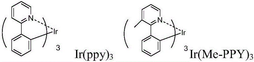
[0107] Using different organometallic iridium light-emitting complexes and host materials, OLED light-emitting devices were fabricated and examined for comparison. Comparative known organometallic iridium complex materials used:

[0108]

[0109] Compare with known host materials:

[0110]

[0111] Table 5: Performance of vacuum-evaporated OLED devices (room temperature@1000nits)

[0112]

[0113] Compared with comparative devices A and B, Table 5 illustrates that the organometallic iridium complex light-emitting dopant material of the present invention is applied to OLED light-emitting devices relative to the contrasting green light doping material Ir(pCz)3 and the contrasting red light doping The material ...

Embodiment 3

[0114] Embodiment 3 solution is made OLED device:

[0115] On the surface of a conductive glass ITO, after solvent and plasma cleaning, the solution is spin-coated with PEDOT conductive polymer as the hole injection layer, and the poly(triphenylamine-9.9-diheptane fluorene) PTW solution spin-coated film is used as the hole transport layer. , then use 2% host material DBTT / luminescent dopant green light or red light (doping concentration 8% by weight) mixed solution to spin-coat, and then heat to 160 ° C for 30 minutes under nitrogen to make the film become infusible Insoluble; second spin coat with solution Finally in a background vacuum up to 10 -5 In Pa's multi-source evaporation OLED preparation equipment, the electron injection layer is evaporated Preparation of OLED devices ITO / PEDOT / PTW / DBTT: 5% light-emitting dopant / TPBi / LiF / Al.

[0116] Table 6: Performance of solution spin-coated OLED devices (room temperature@1000nits)

[0117]

[0118] Comparing Devices C a...


PUM

PropertyMeasurementUnit
Luminous wavelengthaaaaaaaaaa

Abstract

The invention discloses an organic metal iridium complex (or hybrid iridium complex). The structure of the complex is as shown in the specification, a developed indolocarbazole series serves as a unit portion of an organic metal iridium light-emitting ligand structure, the charge transfer capacity of the conjugate iridium complex is increased, the performance of an OLED (organic light-emitting diode) device can be improved, the dissolving performance of the light-emitting iridium complex can be enhanced, sublimation temperature is reduced, and a plurality of original difficultly dissolved, sublimated and purified light-emitting iridium complexes are easily dissolved, sublimated and evaporated on a large scale to prepare the OLED device.

Description

[0001] Technical field: [0002] The invention relates to a light-emitting organic metal iridium complex and an organic electroluminescent device prepared therefrom. The use of an improved light-emitting metal iridium complex in the light-emitting layer can be applied to organic light-emitting OLED devices, and the charge injection, solubility and processability of light-emitting materials can be improved, which is beneficial to the large-scale production of OLED display devices. [0003] Background technique: [0004] Organic semiconductor materials are new optoelectronic materials, and its large-scale research originated in 1977 by Hideki Shirakawa, A. Heeger and A. McDiamid jointly discovered doped polyacetylene with conductivity up to copper level. Subsequently, in 1987, C.Tang of Kodak Company invented the organic small molecule light-emitting diode (OLED), and in 1990, R.Friend and A.Holmes of Cambridge University invented the polymer light-emitting diode P-OLED, and in 1...

Claims


Application Information

Patent Timeline
IPC IPC(8): C07F15/00C09K11/06H01L51/54
CPCC09K11/06C07F15/0033C09K2211/185H10K85/342
Inventor 李晓常郝望龙洪海兵
Owner GUANMAT OPTOELECTRONICS MATERIALS INC
Why Eureka
Try Eureka