User terminal in quantum key distribution system, MDI-QKD system and method and network system

A quantum key distribution and client-end technology, which is applied in the MDI-QKD system and the key distribution field in quantum secure communication, can solve problems such as restricting the MDI-QKD system, increasing costs, and unfavorable MDI-QKD network expansion.

Active Publication Date: 2017-06-13
ZHEJIANG SHENZHOU QUANTUM NETWORK TECH CO LTD
View PDF4 Cites 35 Cited by
  • Summary
  • Abstract
  • Description
  • Claims
  • Application Information

AI Technical Summary

Problems solved by technology

[0007] 1. The existing MDI-QKD system optical pulse phase encoding requires a phase modulator, and light intensity modulation requires an intensity modulator. The use of these two modulation devices not only limits the high-speed application of the system, but also the complex driving circuits of the two make the user end The structure is bulky and the cost increases, which is not conducive to the network expansion of MDI-QKD
[0008] 2. In the existing MDI-QKD system, the phase reference consistency of the front and back optical pulses sent by a single client needs to be guaranteed by a phase feedback system, and the design project in the networked system is huge
[0009] The above two major defects restrict the networked application of the MDI-QKD system based on phase encoding, especially when it comes to simultaneously ensuring the consistency of the optical pulse phase reference among multiple users, the phase feedback system of the entire network will be a huge engineering design

Method used


Image

  • User terminal in quantum key distribution system, MDI-QKD system and method and network system
  • User terminal in quantum key distribution system, MDI-QKD system and method and network system
  • User terminal in quantum key distribution system, MDI-QKD system and method and network system

Examples


Embodiment 1

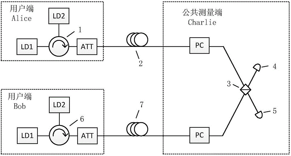
[0091] At the heart of the invention is the use of a modulated light source. Such as image 3 As shown, the modulated light source is composed of two lasers LD1, LD2 and a fiber circulator 1 / 6 connecting the two lasers. The two lasers are respectively used as a phase preparation laser and a pulse generation laser. The optical pulse output by the phase preparation laser is injected into the pulse generating laser through the fiber circulator 1 / 6, and the optical pulse output by the pulse generating laser is output outside through the optical fiber circulator. The output of the modulated light source is essentially the output of the pulsed laser.

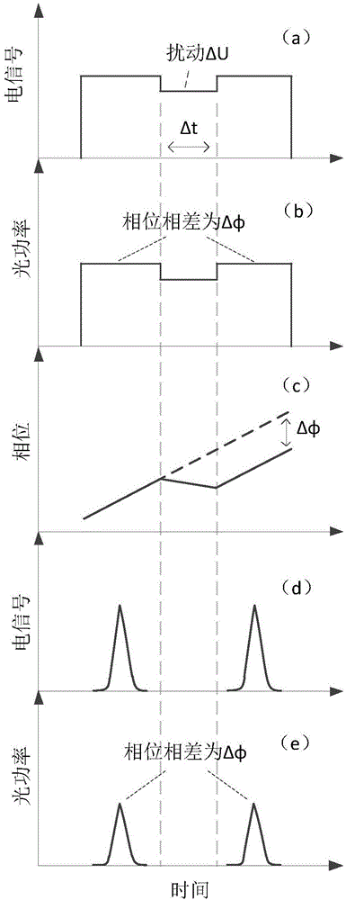
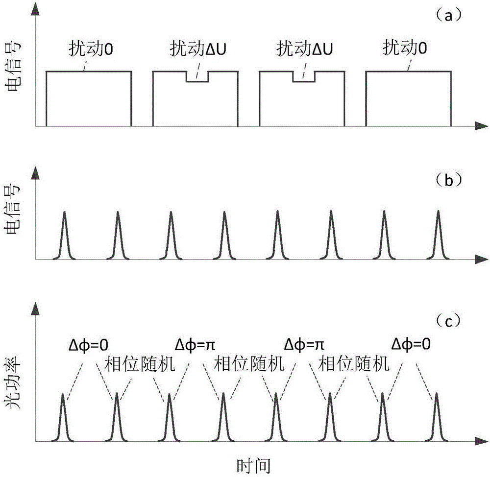
[0092] In particular, when the phase preparation laser and the pulse generation laser work independently, the trigger electrical signals of the two lasers are modulated so that the two lasers emit uniform pulse sequences at equal intervals, and the periods of the two pulse sequences are adjusted so that the phase preparation laser e...

Embodiment 2

[0116] In the first embodiment, the system uses the synchronization module ( image 3 Not shown in ) to control the light pulses emitted by Alice and Bob to reach Charlie's Bell state measuring equipment at the same time. This embodiment gives an example of this synchronization module, such as Figure 7 shown. Because the synchronization of Alice and Bob's two-way signal light is mainly subject to the difference between the two long-distance separated quantum channels 2 and 7, the quantum channel 2 and quantum signal 7 are used as the main path to construct a ring path, so that the user end Alice's synchronization light and The sum of the two paths of the signal light overlaps with this circular path, so that the sum of the two paths of the synchronous light and the signal light of Bob at the user end also overlaps with this circular path. The impact of the path difference between the two on synchronization.

[0117] Figure 7 It is an example diagram of the time synchroni...

Embodiment 3

[0125] Figure 9 It is the optical path diagram of the networked MDI-QKD system based on optical injection. This embodiment is a network expansion based on the point-to-point system of the embodiment, and each client has the same equipment composition and connection mode. The structure of the user end and the public measurement end Charlie, the generation of optical pulses, encoding, decoy state modulation, and detection methods are basically the same as those in Embodiment 1, and the selection of legal Bell states is the same as in Embodiment 1. The difference is that an optical switch 15 and a filter BPF (16 / 17) are added before the Charlie polarization control unit PC. The switching of the optical switch 15 makes the required two user terminals connected to the measurement terminal Charlie, and the two-way filter BFP in Charlie (16 / 17) are used to filter the stray light in the two incoming user optical pulses.


PUM


Abstract

The invention provides a user terminal in a quantum key distribution system. The quantum key distribution system comprises a modulation light source, and the modulation light source comprises a phase preparation laser, an optical fiber circulator and a pulse production laser. The invention further provides a MDI-QKD system, which comprises a user terminal and a public measure terminal, wherein the user terminal comprises an Alice terminal and a Bob terminal; the public measurement terminal is a Charlie terminal; each of the Alice terminal and the Bob terminal comprises the modulation light source. The invention further provides a key distribution method of the MDI-QKD system based on light injection, and a networked MDI-QKD system. The user terminal provided by the invention simplifies a structure of each of a phase modulation laser and the pulse production laser, and is unnecessary to set a phase feedback system. The MDI-QKD system provided by the invention realizes the integrated structure of the light source, the phase modulator and an intensity modulator; the limitation to the system high-speed application by the phase modulator and the intensity modulator are relieved; the modulation light source can directly generate light pulse with pure phase difference information, and the consistency control on multiuser light pulse phase standards can be realized.

Description

technical field [0001] The present invention relates to the field of communication, relates to a user terminal including a quantum key distribution system, in particular to an MDI-QKD system, the technical field of optical fiber transmission quantum secret communication and a key distribution method in quantum secret communication. Background technique [0002] In 2012, Lo et al. proposed a measurement-device-independent QKD (MDI-QKD) protocol, in which Alice and Bob send encoded light pulses to Charlie, an untrusted third party, for Bell State measurement, immune to any detector side channel attack, greatly improving the real security of the QKD system. [0003] The MDI-QKD system based on phase encoding, because of the strong anti-interference ability of optical pulse phase modulation in optical fiber transmission, the system can obtain stable detection results and high coding rate, so it is very suitable for long-distance secure communication between both parties. The ma...

Claims


Application Information

Patent Timeline
Patent Type & Authority Applications(China)
IPC IPC(8): H04B10/50H04B10/508H04B10/524H04B10/54H04B10/548H04B10/80H04L9/08
CPCH04B10/503H04B10/508H04B10/524H04B10/54H04B10/548H04B10/80H04L9/0819H04L9/0852
Inventor 富尧王真真
Owner ZHEJIANG SHENZHOU QUANTUM NETWORK TECH CO LTD
Why Eureka
Try Eureka