Smelting furnace

A smelting furnace and hearth technology, applied in the chemical industry, can solve the problems of increasing negative effects, increasing production costs, reducing product quality and production efficiency, etc., to achieve the effects of improving heat uniformity, reducing energy consumption, and shortening the smelting cycle

Pending Publication Date: 2017-06-20
JIANGSU PROVINCE METALLURGICAL DESIGN INST
View PDF0 Cites 8 Cited by
  • Summary
  • Abstract
  • Description
  • Claims
  • Application Information

AI Technical Summary

Problems solved by technology

[0003] The problem with gas-fired smelting furnaces is that such equipment generally uses natural gas, and for areas lacking natural gas, coke oven gas or coal-to-synthesis gas is used
However, the conversion of coal to syngas has coal heat loss and equipment investment. Therefore, both natural gas and coal-to-synthesis gas have problems such as high price and high energy consumption. High energy consumption and high price directly increase production costs, maki...

Method used


Image

  • Smelting furnace
  • Smelting furnace
  • Smelting furnace

Examples


Embodiment

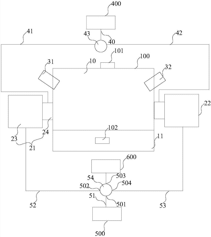
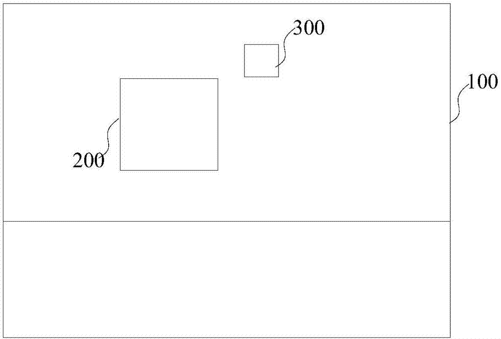
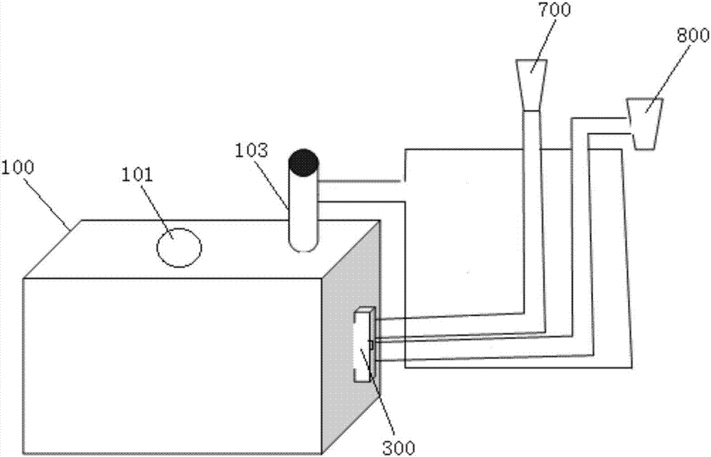
[0059] Such as Figure 1-3As shown, the pulverized coal-gas assisted spray gun is arranged on the melting furnace body, the burner of the first heat storage assembly of the heat storage device of the smelting furnace and the position of the first spray gun assembly of the pulverized coal-gas assisted spray gun are arranged alternately up and down, and the heat storage of the smelting furnace The burners of the second heat storage assembly of the device and the second spray gun assembly of the pulverized coal-gas assisted spray gun are arranged staggered up and down, and the first spray gun assembly and the second spray gun assembly respectively form an angle α=80 with the side wall of the melting furnace body °, the spray gun is arranged at an angle of 90°-α=10° to the horizontal, the flame sprayed by the spray gun is obliquely downward, and the burning flame in the direction of the burner is parallel to the horizontal plane. When the first heat storage component is in the com...


PUM


Abstract

The invention discloses a smelting furnace. The smelting furnace comprises a smelting furnace body, a heat storage device, a coal powder-oxidant gas spray gun, a gas supply assembly, an air supply assembly and a smoke exhaust pipe assembly; a furnace hearth is defined in the smelting furnace body, the heat storage device comprises a first heat storage assembly and a second heat storage assembly, the first heat storage assembly and the second heat storage assembly each comprises a heat storage combustion chamber and a combustion nozzle which are connected with each other, and each heat storage combustion chamber communicates with the corresponding combustion nozzle through the furnace hearth; the coal powder-oxidant gas spray gun comprises a first spray gun assembly and a second spray gun assembly, the first spray gun assembly and the second spray gun assembly are arranged on the side walls of the smelting furnace body separately, the first spray gun assembly and the first heat storage assembly are distributed on the side wall of the smelting furnace body in a staggered manner, and the second spray gun assembly and the second heat storage assembly are distributed on the side wall of the smelting furnace body in a staggered manner; and the gas supply assembly is connected with the combustion nozzle of the first heat storage assembly and the combustion nozzle of the second heat storage assembly separately, the air supply assembly is connected with the heat storage combustion chamber of the first heat storage assembly and the heat storage combustion chamber of the second heat storage assembly separately, and the smoke exhaust pipe assembly communicates with the heat storage combustion chamber of the first heat storage assembly and the heat storage combustion chamber of the second heat storage assembly separately.

Description

technical field [0001] The invention belongs to the technical field of chemical industry, in particular, the invention relates to a melting furnace. Background technique [0002] Gas melting furnace with its SO 2 , NO x It is widely used in metallurgy and foundry processing industries due to its low emission, cleanliness, convenient operation and easy automatic control. It is a smelting equipment commonly constructed and used. [0003] The problem with gas-fired smelting furnaces is that this type of equipment generally uses natural gas, and for areas lacking natural gas, coke oven gas or coal-to-synthesis gas is used. However, the conversion of coal to syngas has coal heat loss and equipment investment. Therefore, both natural gas and coal-to-synthesis gas have problems such as high price and high energy consumption. High energy consumption and high price directly increase production costs, making enterprises lack market economic competitiveness. At the same time, the ne...

Claims


Application Information

Patent Timeline
IPC IPC(8): F27B14/14F23D17/00
CPCF27B14/14F23D17/005F23D2204/20F27D99/0033F27D2099/0055F27D2099/0056F27M2003/13
Inventor 邓君薛逊曹志成冯鲁兴唐敬坤韩志彪吴道洪
Owner JIANGSU PROVINCE METALLURGICAL DESIGN INST
Why Eureka
Try Eureka