Mixed dielectric barrier discharging device

A technology of barrier discharge and discharge device, applied in the field of plasma, can solve the problems of inability to combine dielectric barrier discharge and creeping discharge, insufficient electron temperature and electron density, and low discharge energy utilization rate, etc. The effect of mitigating adverse effects and compact device structure

Pending Publication Date: 2017-06-23
DALIAN MARITIME UNIVERSITY +1
View PDF7 Cites 4 Cited by
  • Summary
  • Abstract
  • Description
  • Claims
  • Application Information

AI Technical Summary

Problems solved by technology

However, this design is limited by the dielectric layer and structure design used, and the electron temperature and electron density in the plasma are not high enough, so although the discharge energy utilization rate is improved, it is far below the theoretical value.
To sum up, the existing technology has defects such as low energy utilization rate and complex structure, and cannot effectively combine dielectric barrier discharge and creeping discharge.

Method used


Image

  • Mixed dielectric barrier discharging device
  • Mixed dielectric barrier discharging device
  • Mixed dielectric barrier discharging device

Examples


Embodiment 1

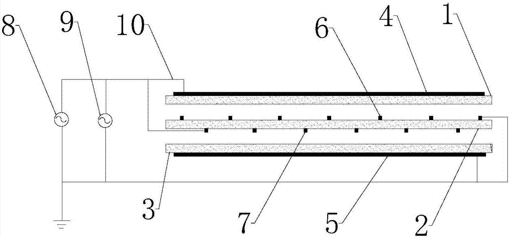
[0036] figure 1Shown is a schematic diagram of a hybrid dielectric barrier discharge device of the present invention. The device is preferably composed of three uniform aluminum oxide flat dielectric layers arranged in parallel; the thickness of each dielectric layer is 0.1-1.5mm, and the gas gap between each adjacent two dielectric layers is 0.1-2mm. A thin metal electrode is attached to the upper surface of the top dielectric layer 1; a thin metal electrode is attached to the lower surface of the bottom thin dielectric layer 3; and a grid-shaped metal electrode is attached to the upper and lower surfaces of the intermediate dielectric layer 2 respectively. The thickness of each grid-shaped metal electrode and sheet metal electrode is 0.01-1.5mm, the width of each grid-shaped electrode metal strip is 1-5mm, and the distance between adjacent metal strips is 1-5mm. A grid-shaped metal electrode metal strip on the lower surface of the intermediate dielectric layer is correspond...

Embodiment 2

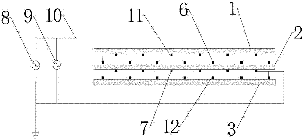
[0041] figure 2 Shown is a schematic diagram of another hybrid dielectric barrier discharge device of the present invention. The mixed discharge reactor is composed of three uniform aluminum oxide flat dielectric layers arranged in parallel; the thickness of the dielectric layer is 0.1-1.5mm, and the gas gap between each adjacent two dielectric layers is 0.1-2mm. A grid-shaped metal electrode 11 is attached to the lower surface of the top dielectric layer 1; a grid-shaped metal electrode 12 is also attached to the upper surface of the bottom dielectric layer 3; and a grid-shaped metal electrode 6 and 7 are respectively attached to the upper and lower surfaces of the intermediate dielectric layer 2. . The thickness of the grid electrodes used is 0.01-1.5 mm, the width of the metal strips is 1-5 mm, and the distance between adjacent metal strips is 1-5 mm. A grid-shaped metal electrode metal strip on the lower surface of the intermediate dielectric layer is correspondingly ar...

Embodiment 3

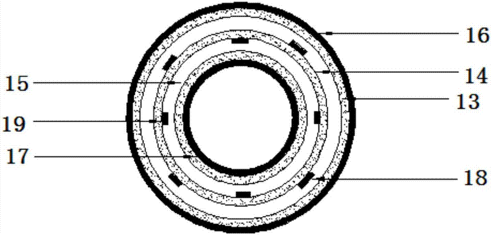
[0045] image 3 It is a schematic diagram of a cylindrical mixed dielectric barrier discharge device of the present invention, which is a further improvement on Example 1 as a preferred embodiment of the present invention. The device is composed of three uniform aluminum oxide cylindrical dielectric layers concentrically nested; the thickness of the dielectric layer is 0.1-1.5mm, and the radius of each adjacent cylindrical dielectric layer decreases sequentially from the outside to the inside, so that the gas gap between the dielectric layers is uniform 0.1 ~ 2mm. A sheet metal electrode 16 is attached to the outer surface of the outermost cylindrical dielectric layer 13; a thin sheet metal electrode 17 is also attached to the inner surface of the innermost cylindrical dielectric layer 15; Shaped metal electrodes 18 and 19. The thickness of the grid-shaped metal electrode 18 on the outer surface of the middle cylindrical dielectric layer 14, the grid-shaped metal electrode 1...


PUM

PropertyMeasurementUnit
thicknessaaaaaaaaaa
thicknessaaaaaaaaaa
widthaaaaaaaaaa

Abstract

The invention discloses a mixed dielectric barrier discharging device comprising an alternating-current high-voltage power supply, dielectric layers with uniform materials, metal electrodes, wires and an oscilloscope. The metal electrodes are attached to the surfaces of the dielectric layers and narrow discharge gaps are formed between adjacent dielectric layers. An alternating-current voltage is applied to an electrode terminal, so that bulk phase dielectric barrier discharging and discharging along the dielectric surface can be carried out simultaneously at the same discharge gap. In addition, a multi-channel discharge gap structure having high electric field strength is established in the discharging device by increasing the number of the dielectric layers in the discharging device. Compared with the conventional dielectric barrier discharging or discharging along the dielectric surface, the mixed dielectric barrier discharging enables the energy utilization rate to be improved and the application range can be extended. Moreover, the structure is compact; assembling becomes convenient and flexible; maintenance becomes convenient; and amplification and upgrading can be done easily; and practicability is high.

Description

technical field [0001] The invention belongs to the technical field of non-thermal discharge plasma, and in particular relates to a mixed dielectric barrier discharge device. Background technique [0002] Bulk dielectric barrier discharge and creeping discharge can generate a large area of ​​plasma area under atmospheric pressure and the discharge is uniform and stable. The structure of the discharge device is simple and the dynamic response is fast. Therefore, it has broad application prospects in the fields of material surface treatment, biomedicine, and environmental protection. . Generally, in order to realize bulk dielectric barrier discharge or creeping discharge, an insulating medium (such as glass, ceramic and quartz, etc.) needs to be placed between a high-voltage electrode composed of a metal sheet or a grid-shaped metal strip and a ground electrode, and an AC power supply is used to pass through The wire connects the two ends of the high-voltage electrode and the...

Claims


Application Information

Patent Timeline
Patent Type & Authority Applications(China)
IPC IPC(8): H05H1/24
CPCH05H1/2406H05H1/2418
Inventor 朱益民李猛朱斌王宁会李铁唐晓佳
Owner DALIAN MARITIME UNIVERSITY
Why Eureka
Try Eureka