Extraction separation device used for catalytic cracking clarified oil and extraction separation method thereof

A catalytic cracking and separation device technology, applied in the direction of separation methods, chemical instruments and methods, chemical/physical/physicochemical processes using energy, etc., can solve the problems of high extraction pressure, low extraction rate, complicated operation, etc., and achieve extraction High efficiency, shortened operating time, reduced temperature and pressure effects

Pending Publication Date: 2017-06-30
ENERGY & ENVIRONMENT RES INST OF HEILONGJIANG PROVINCE
View PDF12 Cites 1 Cited by
  • Summary
  • Abstract
  • Description
  • Claims
  • Application Information

AI Technical Summary

Problems solved by technology

[0004] The invention aims to solve the technical problems of complex operation, high extraction pressure and low extraction rate in the pretreatment of catalytic cracking oil slurry

Method used


Image

  • Extraction separation device used for catalytic cracking clarified oil and extraction separation method thereof
  • Extraction separation device used for catalytic cracking clarified oil and extraction separation method thereof

Examples


specific Embodiment approach 1

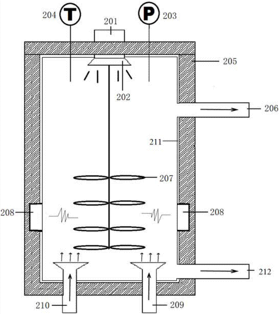
[0019] Specific Embodiment 1: In this embodiment, the ultrasonic and microwave-enhanced supercritical fluid extraction device includes: a tank body 211, an ultrasonic generator 201, an ultrasonic transducer 202, a pressure gauge 203, a thermometer 204, a heating insulation jacket 205, and a stirring paddle 207 and a microwave generator 208, wherein the ultrasonic generator 201 is arranged outside the top of the tank body 211, the ultrasonic transducer 202 is arranged inside the top end of the tank body 211, a pressure gauge 203 and a temperature gauge 204 are set near the ultrasonic generator 201, and the microwave The generator 208 is arranged on the side wall of the tank body 211, the bottom of the tank body 211 is provided with a solvent inlet 209 and a substance to be extracted inlet 209, the upper side wall of the tank body 211 is provided with a mixture outlet 206, and the stirring paddle 207 is vertically arranged on the inside of the tank body 211. In the middle positio...

specific Embodiment approach 2

[0020] Specific embodiment two: the difference between this embodiment and specific embodiment one is: the thickness of the heating insulation jacket 205 is 10-100 mm, and the insulation material is one of polyurethane foam, perlite insulation layer, benzene board, extruded plastic board and polyethylene One or more composite materials. Others are the same as in the first embodiment.

specific Embodiment approach 3

[0021] Embodiment 3: This embodiment differs from Embodiment 1 or Embodiment 2 in that: the height of the microwave generator 208 is 1 / 3 of the tank body 211 . Others are the same as in the first or second embodiment.


PUM


Abstract

The invention discloses an extraction separation device used for catalytic cracking clarified oil and an extraction separation method thereof, and relates to the field of devices for pretreatment of catalytic cracking oil slurry. The technical purpose is to solve the technical problem that an existing supercritical fluid extraction device is high in extraction pressure and low in extraction rate in catalytic cracking oil slurry pretreatment. The device comprises a tank body, an ultrasonicator, an ultrasonic transducer, a pressure gauge, a temperature meter, a thermal insulation jacket, an agitator blade and a microwave generator, wherein the ultrasonicator is arranged at the outer side at the top end of the tank body, the ultrasonic transducer is arranged on the inner side of the top end of the tank body, the microwave generator is arranged on the side wall of the tank body, the bottom of the tank body is provided with a solvent inlet and an inlet of an object to be extracted, and the side wall at the upper portion of the tank body is provided with a mixture outlet. The method comprises the first step of conducting feeding, the second step of conducting mixed heating, and the third step of raising the pressure to conduct extraction. Under an ultrasound and microwave effect, the extraction separation device lowers the supercritical fluid extraction temperature and pressure, shortens the operation time, and improves the extraction efficiency. The extraction separation device is used in pretreatment of the catalytic cracking oil slurry.

Description

technical field [0001] The invention relates to the field of devices for catalytic cracking oil slurry pretreatment, in particular to an extraction device and an extraction and separation method thereof. Background technique [0002] The crude oil refining process usually involves technologies such as catalytic cracking, and a large amount of catalytic cracking oil slurry is produced in this process. Catalytic cracking oil slurry has the characteristics of high density, low H / C atomic ratio, high saturated content, low colloid and asphaltene content, and can be separated to produce high value-added chemical products such as needle coke and mesophase pitch. product. However, catalytic cracking oil slurry is inferior heavy oil, which contains a large number of catalyst particles. If it is directly used, these solid particles will seriously affect the deep processing products of oil slurry and downstream equipment, which is not conducive to the comprehensive utilization of oil...

Claims


Application Information

Patent Timeline
IPC IPC(8): B01D11/04C10G21/00B01J19/10
CPCB01D11/0423C10G21/00
Inventor 杨光陈松徐晓秋李福裿
Owner ENERGY & ENVIRONMENT RES INST OF HEILONGJIANG PROVINCE
Why Eureka
Try Eureka