

Variable dimension vibrating auxiliary drilling device and track generation method
A technology of vibration trajectory and generation method, which is applied in the direction of fluid, turning equipment, drilling tool accessories, etc. using vibration, can solve the problems of inability to adjust the parameters of the drilling device, small amplitude, and inability to meet the processing requirements of composite materials.
- Summary
- Abstract
- Description
- Claims
- Application Information
AI Technical Summary
Problems solved by technology
Method used
Image

Examples
Embodiment Construction
[0045] The technical solution of the present invention will be described in detail below in conjunction with the accompanying drawings.
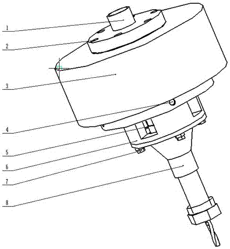
[0046] A vibration-assisted drilling device with multiple vibration forms coexisting, characterized in that:
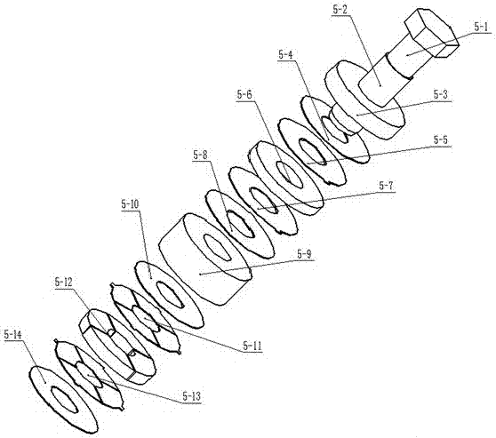
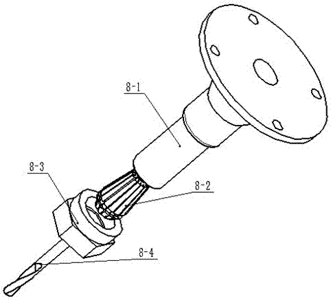
[0047] The device is composed of a machine tool holder 1, a piezoelectric transducer 5, a horn 8, a pre-tightening bolt 5-1, and a tool connection mechanism 8-2, 8-3;
[0048] The tool handle 1 installed on the above machine tool is connected to the variable dimension vibration drilling device to the machine tool workbench;
[0049] The above-mentioned piezoelectric transducer 5 is arranged with radial piezoelectric ceramic groups 5-12 and axial piezoelectric ceramic groups; also arranged with electrode sheets, insulating gaskets, and isolating axial displacement signals and radial displacement signals , the intermediate spacer 5-9 that reduces the coupling between the two; wherein the radial piezoelectric ceramic group 5-12 is div...
PUM
 Abstract
Description
Claims
Application Information