A Method for Calculating the Temperature of Materials Bombarded by Ion Beams Using Computer Simulation

A computer simulation and ion beam technology, applied in the field of ion beam applications, can solve the problems of waste of manpower and material resources, troublesome temperature measurement, long test preparation time, etc., to achieve the effect of avoiding preparation and improving work efficiency

Inactive Publication Date: 2020-05-08
NANJING INST OF ASTRONOMICAL OPTICS & TECH NAT ASTRONOMICAL OBSE
View PDF4 Cites 0 Cited by
  • Summary
  • Abstract
  • Description
  • Claims
  • Application Information

AI Technical Summary

Problems solved by technology

[0004] At present, in the prior art, for the measurement of the surface temperature of the bombarded material, the general measurement method is to indirectly measure the temperature generated by the ion beam bombarding a certain material experimentally, but the actual temperature measurement test requires a long test preparation time , and the recording and analysis of the test data during the test and the processing of the post-test data also take a long time, which caused a lot of trouble to the temperature measurement of the bombarded material in practice, and wasted manpower and material resources

Method used

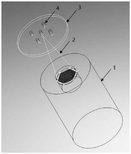
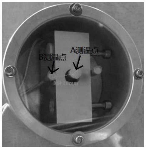
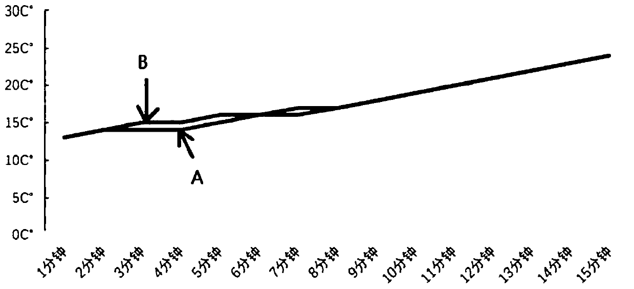

Image

  • A Method for Calculating the Temperature of Materials Bombarded by Ion Beams Using Computer Simulation
  • A Method for Calculating the Temperature of Materials Bombarded by Ion Beams Using Computer Simulation
  • A Method for Calculating the Temperature of Materials Bombarded by Ion Beams Using Computer Simulation

Examples


Embodiment Construction

[0039] The present invention will be described in further detail below in conjunction with the accompanying drawings and embodiments.

[0040] The process of adopting the inventive method to obtain the temperature measurement curve is as follows:

[0041] Step 1: Calculate the ion beam energy density distribution function

[0042] 1. Use an ion beam to etch the material to be bombarded at a fixed point and time, and the etching time is 1.5 minutes. Before and after ion beam bombardment, use a laser interferometer to measure the surface data on the surface of the bombarded material, use the surface data before bombardment to subtract the surface data after bombardment to get the etching amount and divide it by the etching cost Time to obtain the etching rate per unit time of the bombarded material (hereinafter referred to as the material removal work function);

[0043] Material removal work function = (bombing front type data-bombing back type data) / bombing time;

[0044] 2...


PUM


Abstract

The invention discloses a method for calculating the temperature of a material by ion beams through utilizing computer simulation, and aims to overcome the defect of inconvenience of measuring the temperature of the bombarded material through an artificial experiment. By utilizing a computer simulation technology, through thermodynamics simulation analysis, a curve, changed with time, of the temperature of the material bombarded by the ion beams is subjected to analog simulation, so that the temperature curve of the bombarded material can be obtained only by changing parameters of the bombarded material in practical use. According to the method, a conventional mode of measuring the temperature of the material bombarded by the ion beams through the experiment is changed; technical staffs are freed from the tedious actual temperature measurement experiment; preparation of actual temperature measurement experiments, recording and analysis of experiment data and processing of later experiment data are avoided; the working efficiency of scientific and research personnel in researching various material properties by utilizing the ion beams is greatly improved; and a space of prevention in advance can be provided for adverse conditions caused by increased temperature of the bombarded material more conveniently.

Description

technical field [0001] The invention relates to a method for calculating the temperature of materials bombarded by ion beams, belonging to the technical field of ion beam applications. Background technique [0002] The ion beam is under vacuum conditions. After ionizing the inert gas in the ionization chamber of the ion source, after steps such as acceleration and clustering, an ion flow with a certain speed and a certain beam energy is obtained. The most used is the argon ion. . Ion beams are generally used in the following four aspects: ① ion etching; ② ion beam sputtering deposition coating; ③ ion beam sputtering assisted coating; ④ ion implantation. [0003] During the bombardment process of the ion beam on the surface of the material, part of its kinetic energy is transferred to the surface of the bombarded material, causing the surface temperature of the material to rise. Since the process is carried out in a vacuum, it is very unfavorable for heat dissipation (there ...

Claims


Application Information

Patent Timeline
Patent Type & Authority Patents(China)
IPC IPC(8): G06F30/23G06F119/08
CPCG06F30/23G06F2119/08Y02E60/00
Inventor 梁斌郑奕
Owner NANJING INST OF ASTRONOMICAL OPTICS & TECH NAT ASTRONOMICAL OBSE
Why Eureka
Try Eureka