Method for increasing partial hydrogen pressure of hydrogenation reaction system, and design method and application thereof

A technology of hydrogenation reaction and hydrogen partial pressure, which is applied in the field of increasing the hydrogen partial pressure of the hydrogenation reaction system and increasing the hydrogen partial pressure. It can solve the problems of limiting the hydrogenation reaction depth, occupation, and unfavorable hydrogenation reaction, so as to improve the conversion of raw materials. efficiency, reduce energy consumption, and increase the yield of light oil

Inactive Publication Date: 2017-07-18
CATECH TECH
View PDF4 Cites 3 Cited by
  • Summary
  • Abstract
  • Description
  • Claims
  • Application Information

AI Technical Summary

Problems solved by technology

However, for the hydrogenation process with multi-stage reactors, other gases generated in the upper-stage reactor occupy the partial pressure...

Method used


Image

  • Method for increasing partial hydrogen pressure of hydrogenation reaction system, and design method and application thereof
  • Method for increasing partial hydrogen pressure of hydrogenation reaction system, and design method and application thereof
  • Method for increasing partial hydrogen pressure of hydrogenation reaction system, and design method and application thereof

Examples


Embodiment 1

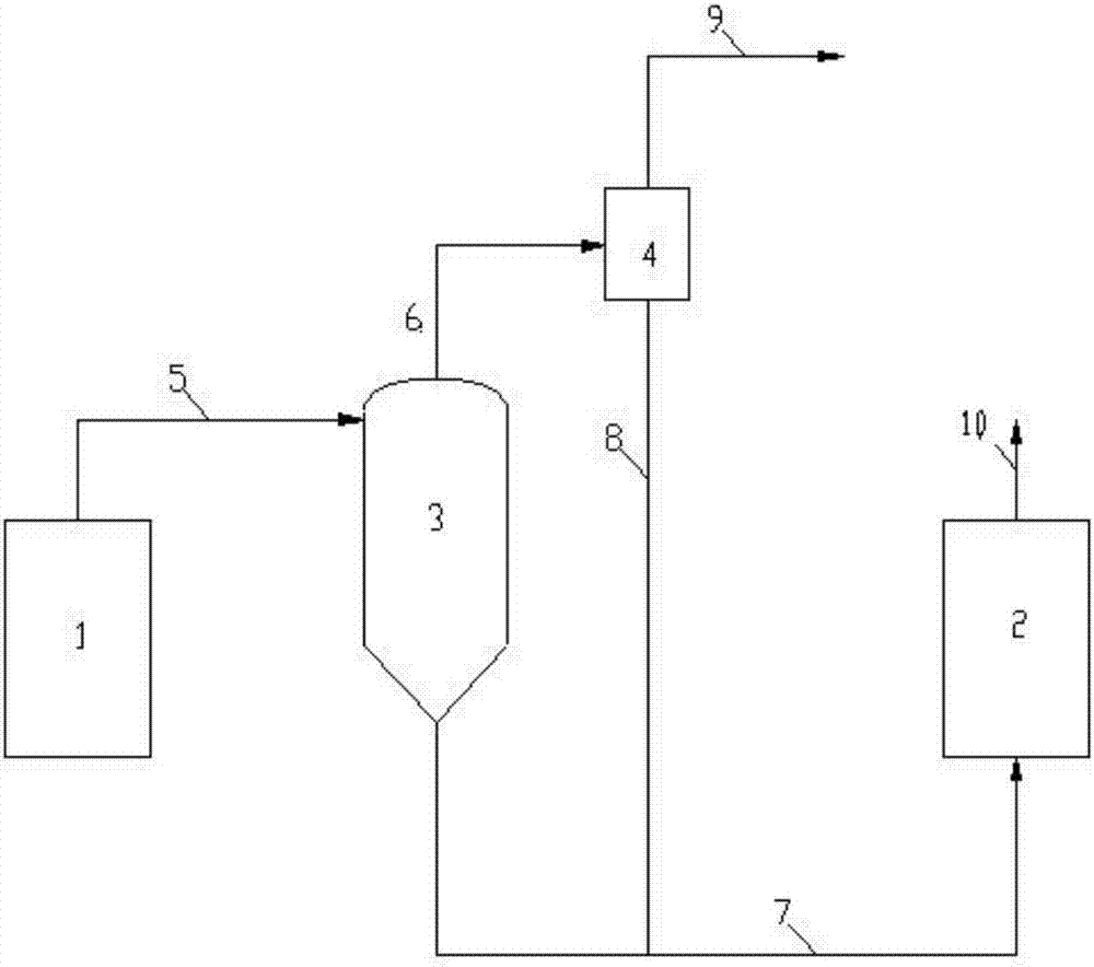
[0030] This embodiment is a slurry bed hydrogenation process for co-refining of oil and coal. Such as figure 1 As shown, the oil-coal mixing slurry bed hydrogenation system includes two-stage reactors, that is, the primary reactor 1 and the secondary reactor 2, and the booster set between the primary reactor 1 and the secondary reactor 2 The hydrogen partial pressure separation system consists of a primary separator 3 and a gas phase separation device 4, wherein the lower end of the primary separator 3 can be a conical structure to facilitate the smooth flow of the liquid-solid phase in the separated product.

[0031] The process flow is as follows: the primary reaction product 5 obtained after the oil-coal mixture is reacted in the primary reactor 1 enters the primary separator 3 for separation, the residence time is 10 minutes, and the operating temperature and operating pressure are the same as those of the primary reactor. 1 are consistent with 450°C and 19MPa respectivel...

Embodiment 2

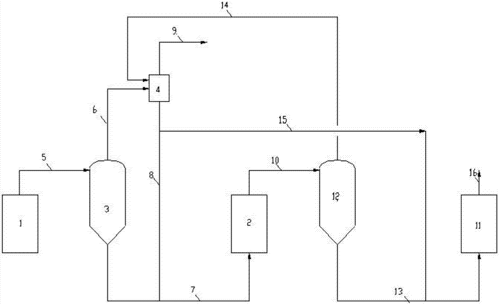
[0037] This embodiment is a vacuum residue slurry bed reaction process. Such as figure 2 As shown, the vacuum residue slurry bed hydrogenation system includes three reactors, that is, the first reactor 1, the second reactor 2 and the third reactor 11, and two sets of hydrogenation reactors arranged between the reactors. Partial pressure separation system: a primary separator 3 and a gas phase separation device 4 arranged between the primary reactor 1 and the secondary reactor 2, a secondary separator between the secondary reactor 2 and the tertiary reactor 11 Stage separator 12 and gas phase separation device 4. In order to save equipment, the two sets of separation systems share one gas phase separation device 4, of course, different gas phase separation devices can also be used respectively. In addition, the lower ends of the primary separator 3 and the secondary separator 12 are conical structures, which facilitate the smooth flow of the liquid-solid phase in the separat...


PUM


Abstract

The invention provides a method for increasing the partial hydrogen pressure of a hydrogenation reaction system, and a design method and an application thereof, which are used for increasing the partial hydrogen pressure of the hydrogenation reaction system and belong to the fields of petroleum chemistry and coal chemistry. The hydrogenation reaction system comprises at least two reactors. The method comprises the following steps that materials discharged from the former-stage reactor firstly enter a separating system for increasing the partial hydrogen pressure to conduct separation, then non-hydrogen components obtained are separated and discharged, and hydrogen components and liquid-solid phases enter the next-stage reactor. The materials from an outlet of the former-stage reactor are effectively separated by the separating system, the liquid-solid phase enters the next-stage reactor, and the gas phase is separated again, so that after the concentration of the hydrogen in the gas phase is increased, and the hydrogen enters the next-stage reactor. The method provided by the invention has the advantages that the partial hydrogen pressure of the next-stage reactor can be increased, the reaction depth can be effectively increased, the material conversion ratio and the light-oil yield can be increased, the space speed of the next-stage reactor also can be increased and the energy consumption can be reduced.

Description

technical field [0001] The invention relates to a method for increasing the partial pressure of hydrogen, in particular to a method for increasing the partial pressure of hydrogen in a hydrogenation reaction system and its design method and application, belonging to the fields of petrochemical and coal chemical industries. Background technique [0002] In recent years, with the continuous increase of crude oil extraction and the continuous decrease of conventional crude oil reserves, the trend of crude oil inferiority has become more and more serious. Among the middle distillate oil obtained by direct distillation of crude oil and the middle distillate oil obtained by secondary processing such as coking and catalytic cracking, etc. The S and N content of the carbon dioxide also increased accordingly. At the same time, with the increasing market demand for light oil and the increasing awareness of environmental protection, environmental protection laws and regulations have st...

Claims


Application Information

Patent Timeline
IPC IPC(8): C10G67/02
CPCC10G67/02C10G2300/4012
Inventor 李苏安邓清宇王坤朋
Owner CATECH TECH
Why Eureka
Try Eureka