Combined type radial dust removal and denitration reactor

A denitration reactor and combined technology, applied in chemical instruments and methods, dispersed particle filtration, gas treatment, etc., can solve the problems of large floor space, secondary pollution, and large catalyst consumption.

Pending Publication Date: 2017-07-21
安徽晨晰洁净科技有限公司
View PDF8 Cites 1 Cited by
  • Summary
  • Abstract
  • Description
  • Claims
  • Application Information

AI Technical Summary

Problems solved by technology

[0005] 1. SCR denitrification catalysts can be divided into two types: high-temperature catalysts (300-400°C) and medium-low temperature catalysts (180-300°C): high-temperature catalysts have been widely used in the power industry, and the technology is very mature; A few industries such as coking and glass still have certain technical risks. The main risk is the dust resistance and sulfur resistance of the catalyst. At the same time, the traditional SCR denitration catalyst generally adopts the honeycomb body model, modular assembly, and the denitrification device occupies a large area. One-time investment High, in addition, the space velocity is low, the amount of catalyst is...

Method used


Image

  • Combined type radial dust removal and denitration reactor
  • Combined type radial dust removal and denitration reactor
  • Combined type radial dust removal and denitration reactor

Examples


no. 1 example

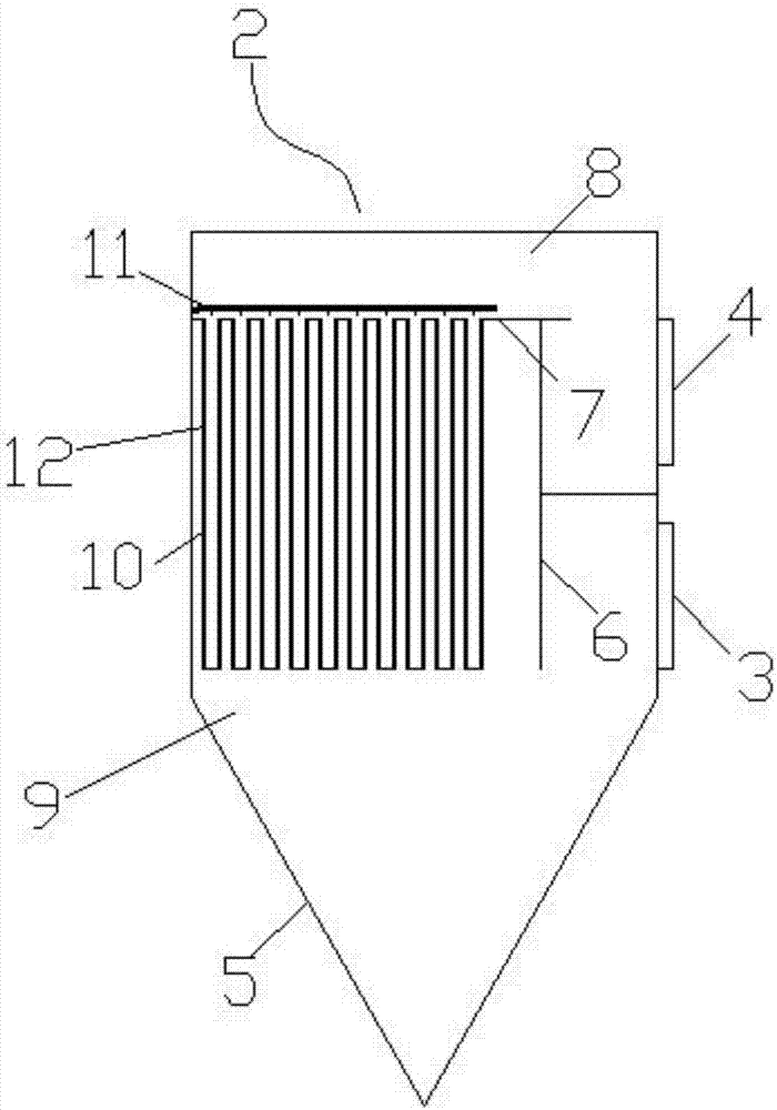
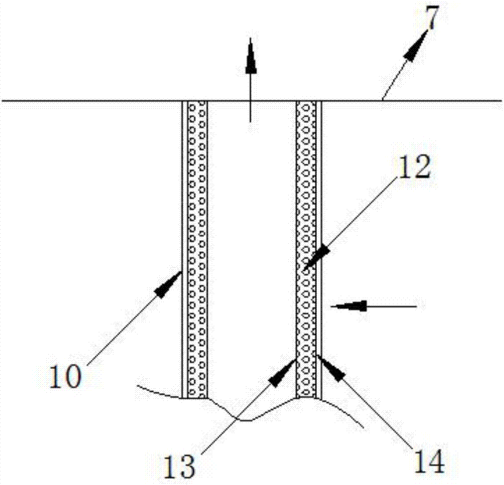
[0032] figure 2 is the schematic diagram of the first embodiment of the radial denitration bed, image 3 It is a partial view of the first embodiment.

[0033] like Figures 2 to 3 As shown, the radial denitration bed 12 is a bag-cage structure, and its shape is cylindrical, each radial denitration bed 12 corresponds to a dust removal bag 10, and the radial denitration bed 12 is close to the inner surface of the dust removal bag 10. , inserted into the bag cage of the dust filter bag 10, the radial denitration bed 12 includes an inner wall 13 and an outer wall 14, the inner wall 13 and the outer wall 14 are both mesh-shaped, and there is a space between the inner wall 13 and the outer wall 14 for flue gas Granular medium and low temperature SCR denitration catalyst for denitration.

no. 2 example

[0035] Figure 4 is the schematic diagram of the second embodiment of the radial denitration bed, Figure 5 A partial view of the second embodiment.

[0036] like Figures 4 to 5 As shown, the radial denitration bed 12 is a cover-type structure, and its shape is cylindrical, each radial denitration bed 12 corresponds to a dust bag 10, and the radial denitration bed 12 is arranged on the flower plate 7 and the soot blowing pipe. Between 11 and 11, the cover is buckled on the flower plate 7, and is located directly above the bag mouth of the dust bag 10. The radial denitration bed 12 includes an inner wall 13 and an outer wall 14, and the inner wall 13 and the outer wall 14 are both mesh-shaped. A granular medium and low temperature SCR denitration catalyst for flue gas denitration is placed between the inner wall 13 and the outer wall 14 .

no. 3 example

[0038] Image 6 It is a schematic diagram of the third embodiment of the radial denitration bed.

[0039] like Image 6As shown in the figure, the radial denitration bed 12 is a warehouse façade type structure, which is a panel shape, is vertically located in the upper warehouse 8 and is close to the part of the flue gas outlet, and its left and right two planes are mesh-shaped, and the two A granular medium and low temperature SCR denitration catalyst for flue gas denitration is placed between the planes.


PUM


Abstract

The invention discloses a combined type radial dust removal and denitration reactor. The combined type radial dust removal and denitration reactor comprises a reactor body, and is characterized in that a plurality groups of chambers for dust removal and denitration of flue gas are mounted in the reactor body; and each chamber is provided with a gas inlet and a gas outlet, the interior of each chamber is divided into an upper chamber and a lower chamber by a division plate and a horizontal pattern plate, the gas inlet is communicated with the lower chamber, the gas outlet is communicated with the upper chamber, a plurality of dust collecting cloth bags are arranged in the lower chamber, bag openings of the plurality of dust collecting cloth bags are buckled on the pattern plate, a soot blowing pipeline is mounted above the pattern plate, a radial denitration bed layer corresponding to the dust collecting cloth bags isalso arranged in the chamber, and the flue gas penetrates through the dust collecting cloth bags and the radial denitration bed layer sequentially in a radial flowing mode. The combined type radial dust removal and denitration reactor provided by the invention is simple and novel in structure, integrates a denitration device and a dust removal device, does not need to add a flue gas uniform distribution device, and reduces investment and equipment floor area while ensuring the denitration efficiency.

Description

technical field [0001] The invention relates to an industrial flue gas purification treatment device, in particular to a combined radial dust removal and denitration reactor. Background technique [0002] my country is a big coal-burning country. Coal burning, coking, glass and other production processes will generate a certain amount of dust, SO 2 , nitrogen oxides and harmful metal elements, etc., NO in flue gas X Emission ratio of SO 2 The harm to the environment is more serious. The emission of a large amount of nitrogen oxides will cause a series of environmental problems such as acid rain, photochemical smog, ozone layer destruction and greenhouse effect, especially the serious "haze" phenomenon that has occurred in most parts of the country in recent years. The root cause is the emission of nitrogen oxides. Controlling the emission of nitrogen oxides in the atmosphere has attracted global attention, and it is also the focus and difficulty of protection in the current...

Claims


Application Information

Patent Timeline
IPC IPC(8): B01D46/02B01D53/86B01D53/56
CPCB01D46/023B01D53/8631B01D2255/9202B01D2258/0283
Inventor 卢昊
Owner 安徽晨晰洁净科技有限公司
Why Eureka
Try Eureka