Pelletizing production line for long-fiber composite material

A composite material, production line technology, applied in the direction of coating, etc., can solve the problem of the degree of infiltration of the material

Active Publication Date: 2017-07-28
BEIJING UNIV OF CHEM TECH
View PDF8 Cites 4 Cited by
  • Summary
  • Abstract
  • Description
  • Claims
  • Application Information

AI Technical Summary

Problems solved by technology

[0007] The purpose of the present invention is to improve the degree of infiltration and dispersion of long fibers in polymer melts, and is committed to solving the problems of long fiber introduction holes and low degree of infiltration in long fiber composite materials, and proposes a manufacturing method for long fiber composite materials. pellet production line

Method used


Image

  • Pelletizing production line for long-fiber composite material
  • Pelletizing production line for long-fiber composite material
  • Pelletizing production line for long-fiber composite material

Examples


Embodiment 1

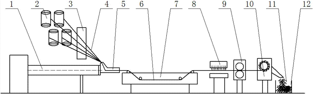
[0078] Such as figure 1The long-fiber composite material granulation production line shown is composed of extruder 1, long-fiber storage unit 2, long-fiber pretreatment unit 3, long-fiber soaking extrusion die 5, cooling system 7, air-drying system 8, traction system 9, Pelletizing system 10 and collection system 12 are made up; Wherein extruder 1 adopts twin-screw extruder (screw diameter 33mm, length-to-diameter ratio 40), to the polypropylene particle that melt index is 60g / 10min, antioxidant (1010 and 168) and the compatibilizer are melted, blended and extruded, and feed the long fiber soaking extrusion die 5 with a certain pressure; the long fiber 4 pulled out from the long fiber storage unit 2 is pretreated by the long fiber pretreatment unit 3 After heating and pre-dividing, the long fiber is introduced into the extrusion die 5, and compounded with the polymer melt to form the polymer wetted long fiber composite material 6; after the polymer wetted long fiber composite ...

Embodiment 2

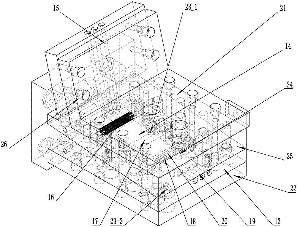
[0087] Based on Example 1, a filament infiltration die having a rectangular cross-sectional filament inlet was used. In order to facilitate the processing of rectangular holes, the mold upper plate is divided into two parts, such as Figure 8 Shown; Compared with embodiment 1, in embodiment 2, the upper plate processing cost of the mold increases to some extent, but the long fiber of 2400tex specification after the long fiber pretreatment unit is processed, after the long fiber of the rectangular cross-sectional shape that is 14mm in width When the fiber is introduced into the inlet, the long fiber is not gathered again; it is more conducive to the infiltration and bonding of the long fiber with the polymer melt in a more dispersed state in the mold.


PUM

PropertyMeasurementUnit
melt flow indexaaaaaaaaaa

Abstract

The invention discloses a pelletizing production line for a long-fiber composite material and belongs to the field of polymer modification equipment. The pelletizing production line comprises an extruder, a long fiber storage unit, a long fiber pretreatment unit, a long fiber wetting extrusion die, a cooling system, an air drying system, a traction system, a pelletizing system and a collecting system. The long fiber wetting extrusion die comprises a molten pool bottom plate, a molten pool upper plate, a guide pillar, an upper heater and a lower heater. A long fiber guide-in hole, a thermocouple installation hole and a melt pressure sensor installation hole are formed in the molten pool upper plate; and an extrusion die hole, a polymer melt feeding port and a thermocouple installation hole are formed in the molten pool bottom plate. A length calculation method for the long fiber guide-in hole and the extrusion die hole of the long-fiber wetting extrusion die is given out. By means of the pelletizing production line for the long-fiber composite material, the staying time of polymer melt in the extrusion die can be effectively shortened, the combining compactness and the wetting degree of long fibers and the polymer melt are improved, and in addition, the phenomena that the polymer melt overflows from the long fiber guide-in hole, and the polymer melt is extruded out of the edge of the die hole, and a polymer is scraped can be avoided.

Description

technical field [0001] The invention relates to a granulation production line for long-fiber composite materials, which belongs to the field of polymer modification equipment. Background technique [0002] In recent years, as the excellent mechanical properties of long-fiber composite materials have attracted more and more attention, more and more scientific and technological workers have carried out a lot of work in the preparation and development of long-fiber composite materials: [0003] 1. Application number: 200610045857.0, titled "Continuous Fiber Reinforced Composite Material, Production Method and Special Equipment", adopts a split flow structure to split the molten polymer, and the long glass fiber introduced at the end of the polymer split flow channel and the vertical direction Converge, and then the long fiber flows out through the serpentine flow channel. There are the following problems in this scheme: the long fiber introduction hole is relatively short, whi...

Claims


Application Information

Patent Timeline
Patent Type & Authority Applications(China)
IPC IPC(8): B29B9/06B29B9/16B29C47/08B29K105/08
CPCB29B9/06B29B9/16B29B2009/168B29C48/251B29K2105/0881
Inventor 毕超郝晓霞
Owner BEIJING UNIV OF CHEM TECH
Why Eureka
Try Eureka