Focused ion beam four-stage grid mesh system achieving fixed point removal and method thereof

A focused ion beam and grid technology, which is applied in the field of focused ion beam four-level grid system, can solve the problems of inability to eliminate fixed-point machining to eliminate surface shape errors, low efficiency of ion source polishing, and equipment introduction, etc., to improve energy density and work efficiency, reduce surface pollution, reduce the effect of loss

Active Publication Date: 2017-08-08
XIAN TECHNOLOGICAL UNIV
View PDF11 Cites 15 Cited by
  • Summary
  • Abstract
  • Description
  • Claims
  • Application Information

AI Technical Summary

Problems solved by technology

However, the research on related equipment and devices is concentrated in the United States and Germany. Since this technology can be applied to sensitive fields such as laser nuclear fusion and laser weapons, these countries still impose a technical blockade on my country in the field of related equipment and its development technology, and cannot directly pass Equipment introduction or technology introduction to make a breakthrough
[0004] At present, the existing ion beam polishing processes in China all use divergent or parallel ion beam equipment. Compared with traditional polishing methods, the polishing efficiency of this type of ion source is low, and it cannot effectively eliminate the surface error of the processed surface by fixed-point processing.

Method used


Image

  • Focused ion beam four-stage grid mesh system achieving fixed point removal and method thereof
  • Focused ion beam four-stage grid mesh system achieving fixed point removal and method thereof
  • Focused ion beam four-stage grid mesh system achieving fixed point removal and method thereof

Examples


Embodiment 1

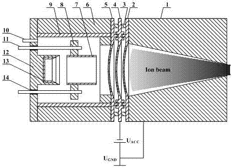
[0038] Embodiment 1, using isostatic graphite grid; screen grid, acceleration grid and grounding grid spherical radius is 80mm; grid spacing 0.25mm; grid aperture diameter 0.5mm, aperture center distance 2 times the diameter, i.e. 1mm ;Parallel opening method, the small holes are arranged in a regular hexagon, and the diagonal length of the figure is 40mm; the grids are insulated by ceramic balls; the measured focus position of the ion beam is 80mm away from the ground grid plane, and the beam spot diameter is 15mm. It is determined that the inlet diameter of the confinement grid is 40mm, the outlet diameter is 15mm, and the length is 70mm; the accelerating voltage is -100V; the ion source operating parameters are: anode voltage 1000V, gas flow rate 15SCCM, working pressure 5×10 -2 Pa; the measured beam current size is 32.7mA.

Embodiment 2

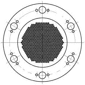
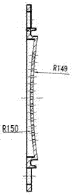
[0039] Example 2 (see figure 2 with image 3 ), using pyrolytic graphite grid; the spherical radius of the screen grid is 150mm, the spherical radius of the accelerating grid and the grounding grid are both 100mm; the grid spacing is 0.5mm; the grid hole diameter is 1mm, and the hole center distance is 1.5 times the diameter, that is, 1.5mm ;Parallel opening method, the small holes are arranged in a regular hexagon, and the diagonal length of the pattern is 40mm; the grids are insulated by ceramic columns; the measured focus position of the ion beam is 85mm away from the ground grid plane, and the beam spot diameter is 20mm. It is determined that the entrance diameter of the confinement grid is 40mm, the exit diameter is 20mm, and the length is 75mm; the accelerating voltage is -200V; the working parameters of the ion source are: anode voltage 1000V, gas flow rate 15SCCM, working pressure 5×10 -2 Pa; the measured beam current size is 31.4mA.

Embodiment 3

[0040] Embodiment 3 (see Figure 4 with Figure 5 ), using metal molybdenum grid; the spherical radius of the screen grid, acceleration grid and grounding grid is 250mm; the grid spacing is 0.5mm; the grid hole diameter is 1mm, and the center distance of the hole is 2 times the diameter, that is, 2mm; parallel opening method (see Image 6 ), the small holes are arranged in a regular hexagon, and the diagonal length of the pattern is 20mm; the grids are insulated by ceramic tubes; the measured focus position of the ion beam is 25mm away from the ground grid plane, and the beam spot diameter is 8mm, so it is determined that the constraint The grid inlet diameter is 20mm, the outlet diameter is 10mm, and the length is 20mm; the accelerating voltage is -1000V; the working parameters of the ion source are: anode voltage 1000V, gas flow rate 15SCCM, working pressure 5×10 -2 Pa; the measured beam current size is 9.8mA.


PUM

PropertyMeasurementUnit
radiusaaaaaaaaaa
surface roughnessaaaaaaaaaa
radiusaaaaaaaaaa

Abstract

The invention relates to a focused ion beam four-stage grid mesh system achieving fixed point removal and a method thereof. With the adoption of a three-stage spherical grid mesh, extraction, shaping and focusing of an ion beam of a wide-beam cold cathode ion source are realized, and a position of an ion beam focus can be adjusted according to the size of the spherical radius of the grid mesh; by changing a distribution map of small holes and the sizes of the small holes in the grid mesh, the size of a beam spot and the size of a beam current are adjusted; and through adjustment on electric potential of an accelerating grid, an ion motion trace can be controlled effectively, and loss and grid mesh loss in an ion motion process can be reduced. The fixed point removal on a processing surface can be realized, and the engineering application of an ion beam technology in China shall be pushed.

Description

technical field [0001] The invention relates to a focused ion beam four-level grid system and method for realizing fixed-point removal. Background technique [0002] In the field of science and engineering technology, the manufacturing technology of ultra-precision optical components is becoming a hot spot of attention. The development of ultra-precision optical components is the requirement of the limit of the development of the optical system itself. The development of modern short-wave optics, strong light optics, electronics, IC technology, information storage technology and thin film science has more stringent requirements on the surface. Generally, the surface with surface roughness better than nanometer level is called ultra-smooth surface. Commonly used ultra-smooth surface processing methods include bath polishing, float polishing and ductile polishing. Although this kind of processing method can obtain extremely low surface roughness, because the traditional proce...

Claims


Application Information

Patent Timeline
Patent Type & Authority Applications(China)
IPC IPC(8): B24B1/00B24B13/00
CPCB24B1/00B24B13/00
Inventor 刘卫国张进惠迎雪周顺陈智利秦文罡
Owner XIAN TECHNOLOGICAL UNIV
Why Eureka
Try Eureka