F-P/ fiber Bragg grating (FBG) fiber sensor demodulation system

A fiber optic sensor and demodulation system technology, applied in the direction of converting sensor output, using optical devices to transmit sensing components, instruments, etc., can solve the problems of stable light source, reduced precision, and difficulties, and achieve simplified devices, reliable performance, and reduced volume effect

Pending Publication Date: 2017-08-08
CHENGDU KAITIAN ELECTRONICS
View PDF13 Cites 19 Cited by
  • Summary
  • Abstract
  • Description
  • Claims
  • Application Information

AI Technical Summary

Problems solved by technology

This method needs to collect a large amount of data in real time, so it affects the demodulation speed
The demodulation principle of the intensity method is simple, but it has the following disadvantages: ①It requires a stable light source
After the light source is affected by external environmental factors, the output light intensity will change, so the accuracy of system measurement will decrease
②According to the principle, high measurement sensitivity can be obtained near the point with better linearity and the largest slope, which requires strict control of the initial cavity length error of the F-P sensor during production, which is relatively difficult
In the current F-P / FBG demodulation system using the scanning principle, optical amplifiers (SOA) and F-P filters are mostly used to realize the ring cavity scanning laser light source, and there are even plans to use ASE and SLED light sources. The problem is that there are many discrete optical devices. Moreover, the components are connected by optical fibers, and the bending radius must be considered. In actual production, they must be fixed with glue and pass the vibration test.
At present, due to the difficulty of demodulation and detection of wavelength-coded signals, the system cost is too high, which is difficult to accept in the general field.

Method used


Image

  • F-P/ fiber Bragg grating (FBG) fiber sensor demodulation system
  • F-P/ fiber Bragg grating (FBG) fiber sensor demodulation system
  • F-P/ fiber Bragg grating (FBG) fiber sensor demodulation system

Examples


Embodiment Construction

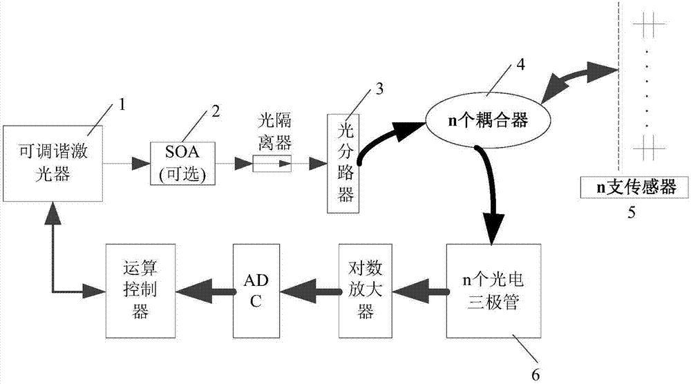
[0024] refer to figure 1 , in the embodiment described below, an optical fiber F-P / FBG wavelength scanning optical fiber tuning system includes: an extrinsic F-P sensing head that does not coat a reflective film, and an external-cavity semiconductor with a micro-electro-mechanical system MEMS. Tuning Laser 1. A semiconductor tunable laser 1 is connected in series with an optical amplifier SOA and / or an optical isolator 2, an optical beam splitter 3, n optical couplers 4, n phototransistors 6, and n phototransistors 6 are sequentially connected in series through a logarithmic amplifier The analog-to-digital converter ADC and the operation controller form a closed loop with the semiconductor tunable laser. Under the control of the operational controller, the tunable laser emits a beam of fixed-wavelength C-band laser, passes through the optical amplifier SOA and / or optical isolator, and splits the incident light equally through the optical beam splitter 3, respectively entering...


PUM


Abstract

The present invention discloses an F-P and FBG fiber sensor demodulation system, and aims to provide an F-P/FBG demodulation system which is high in wavelength resolution, and enables the demodulation precision to be improved. The F-P/FBG fiber sensor demodulation system of the present invention is realized by the following technical scheme that under the control of an operation control unit, a tunable laser emits out a beam of C-wave band laser of a constant wavelength, by an optical amplifier SOA and/or an optical isolator, and by being divided equally via a beam splitter, the incident light respectively irradiates to n F-P/FBG sensors in one-to-one correspondence, the light reflected by the F-P/FBG sensors is coupled to n phototriodes in one-to-one correspondence by n optical couplers, the optical power is converted into an optical current, the optical current is converted into an optical voltage entering an analog-digital converter by a logarithmic amplifier, the wavelength-reflection optical voltage digital quantity acquired in a time-sharing manner is stored in a memorizer of the operation control unit, the operation control unit carries out the fast Fourier transform on a sampled spectrum, the types of the F-P/FBG sensors are distinguished, and a peak searching demodulation algorithm is carried out to obtain a gradient value containing the cavity length information.

Description

technical field [0001] The invention relates to a general demodulation system for F-P / FBG sensors used in the field of optical fiber sensing, which is a demodulation device for F-P and FBG fiber optic sensors proposed mainly for aerospace and aimed at small installation space and light weight requirements. Background technique [0002] The current optical fiber F-P / FBG sensors mainly include FBG and F-P sensors. Among them, FBG has wavelength encoding, easy multiplexing, and dynamic measurement; while optical fiber F-P sensors have static measurement with high precision and low cost. simple features. The signal demodulation technology of the fiber Bragg grating (FBG) sensor is the same as the common demodulation technology. It detects the parameters of the modulated signal of the sensor, and then extracts the information carried by the carrier wave through corresponding calculation processing. According to the sensing principle of the FBG sensor, the FBG sensor modulates th...

Claims


Application Information

Patent Timeline
Patent Type & Authority Applications(China)
IPC IPC(8): G01D5/353
CPCG01D5/35306
Inventor 冯茂乔周力杰李翔
Owner CHENGDU KAITIAN ELECTRONICS
Why Eureka
Try Eureka