
Preparation method of conductive adhesive and conductive adhesive

A technology of conductive glue and conductive balls, applied in the direction of conductive adhesives, non-polymer adhesive additives, adhesive additives, etc., can solve the problems of conductive adhesive conduction, cyanide gold plating toxicity, complex process, etc., to achieve Enhanced electrical conductivity, reduced cost, and ease of deformation

Inactive Publication Date: 2017-08-22
TCL CHINA STAR OPTOELECTRONICS TECH CO LTD
View PDF5 Cites 3 Cited by
  • Summary
  • Abstract
  • Description
  • Claims
  • Application Information

AI Technical Summary

Problems solved by technology

[0005] At present, the cladding metals used in conductive balls in ACF, ACP and other anisotropic conductive adhesives mainly include gold (Au), nickel (Ni), alloys such as gold, silver, or tin plated on nickel, and the gold plating process at home and abroad The cyanide gold plating technology is mainly used, which has certain disadvantages, such as the high toxicity of cyanide gold plating, good ventilation equipment is required during production, and a high level of wastewater treatment is required. In addition, the coating process consumes a lot of energy and the process On the other hand, metal is used as the conductive layer of the conductive ball. Due to the small deformation range of the metal, the metal conductive layer is easily broken when it is deformed under pressure, which may damage the driver chip and the display. At the same time, since the surface of the metal conductive layer of the conductive ball may have horizontal contact, it will also cause the conductive glue to conduct in the horizontal direction

Method used


Image

  • Preparation method of conductive adhesive and conductive adhesive
  • Preparation method of conductive adhesive and conductive adhesive
  • Preparation method of conductive adhesive and conductive adhesive

Examples


Embodiment Construction

[0043] In order to further explain the technical means adopted by the present invention and its effects, the following describes in detail the preferred embodiments of the present invention and the accompanying drawings.

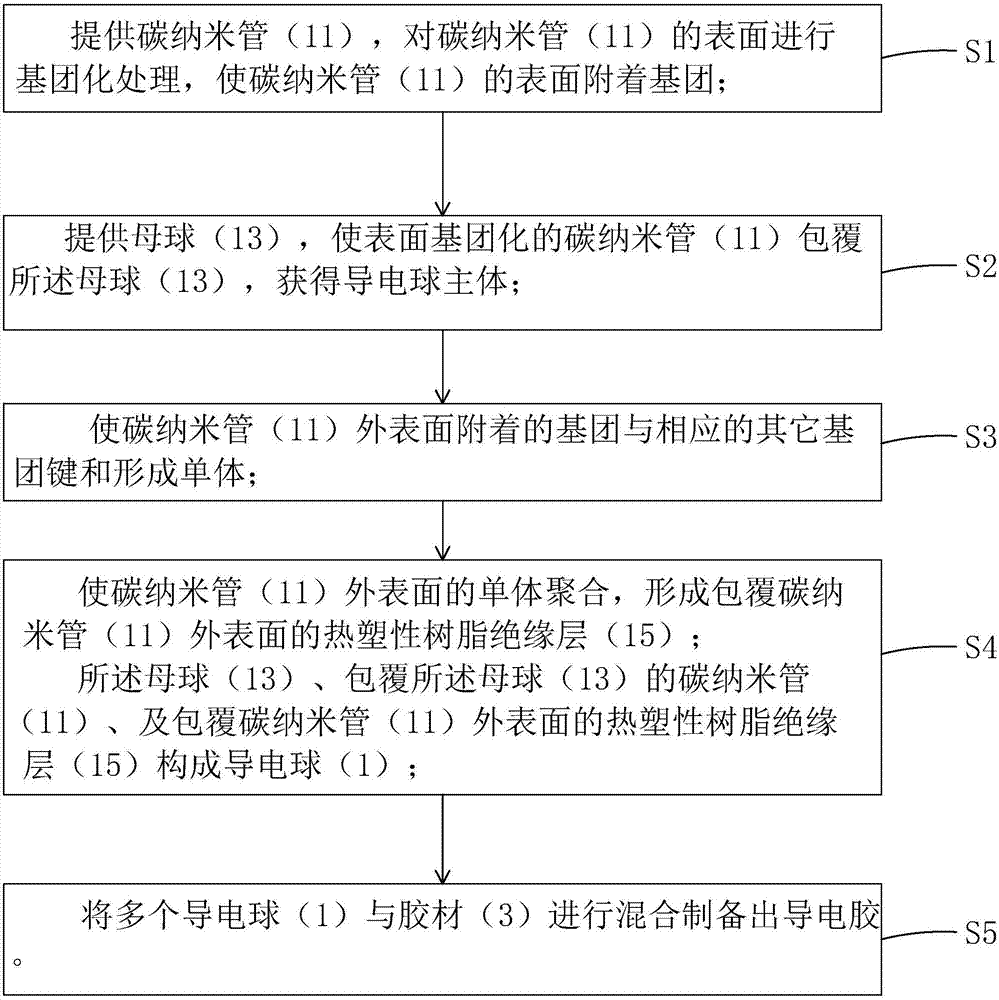
[0044] See figure 1 , The present invention first provides a method for preparing conductive adhesive, including the following steps:

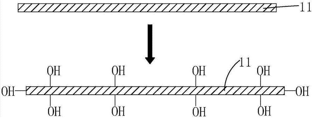
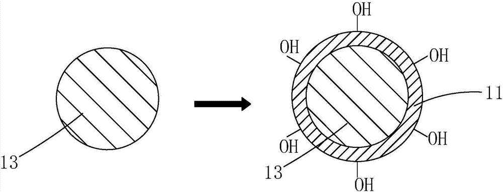
[0045] Step S1, such as figure 2 As shown, carbon nanotubes 11 are provided, and the surface of the carbon nanotubes 11 is grouped to attach groups to the surface of the carbon nanotubes 11.

[0046] Specifically, in the step S1, the surface of the carbon nanotube 11 is hydroxylated, carboxylated, aminated, or acylated, so that the surface of the carbon nanotube 11 is attached with a hydroxyl group (-OH) and a carboxyl group (-COOH). , Amino (-NH2), or acyl (RM(O)-, where M is carbon (C)), etc.

[0047] Taking the step S1 to perform hydroxylation treatment on the surface of the carbon nanotube 11 to make the surface of the carbon n...


PUM


Abstract

The invention provides a preparation method of conductive adhesive and the conductive adhesive. In this method, the surface of carbon nanotubes is grouped first by chemical means, and then the surface grouped carbon nanotubes are coated with cue balls, and then the groups attached to the outer surface of carbon nanotubes are combined with corresponding other groups Group bonds and form monomers, then polymerize the monomers on the outer surface of carbon nanotubes to form a thermoplastic resin insulating layer covering the outer surface of carbon nanotubes to make conductive balls, and finally mix conductive balls with adhesive materials to prepare conductive adhesives The method is simple to operate, does not need cyanide gold plating, and will not cause metal pollution; the prepared conductive adhesive uses soft carbon nanotubes as the conductive layer of the conductive ball, and the outermost layer of the conductive ball is a thermoplastic resin insulating layer, not only The conductivity is improved, and there is no risk of piercing the upper and lower electrodes connected by the conductive adhesive due to the rupture of the metal layer, and it can also prevent the conductive adhesive from conducting in the horizontal direction.

Description

Technical field [0001] The invention relates to the technical field of display device manufacturing processes, in particular to a method for preparing conductive adhesive and conductive adhesive. Background technique [0002] With the rapid development of consumer electronics in the direction of lightness, thinness, and miniaturization, electronic products with LCD (Liquid Crystal Display) and Organic Light Emitting Diode (OLED) display interfaces have been widely used. application. In order to transmit the display signal and control the LCD or OLED, the LCD or OLED must be connected to the driver chip. [0003] The prior art widely uses Anisotropic Conductive Film (ACF) or Anisotropic Conductive Paste (ACP) with anisotropic conductivity to connect the drive chip and the electrodes in the display to make the drive chip Conduction with the display, while avoiding conduction between adjacent electrodes in the horizontal direction. [0004] In the anisotropic conductive glue, the con...

Claims


Application Information

Patent Timeline
Patent Type & Authority Applications(China)
IPC IPC(8): C09J9/02C09J11/04
CPCC09J9/02C08K7/24C08K9/02C08K9/10C08K2201/011C09J11/04
Inventor 王海军
Owner TCL CHINA STAR OPTOELECTRONICS TECH CO LTD
Learn More