
Fluorescent/phosphorescent mixed white light OLED

A phosphorescence and fluorescence technology, which is applied in the field of white light OLED and fluorescent/phosphorescence mixed white light OLED, can solve the complex device structure of multi-emitting layer mixed white light OLED, limit the mass industrial production of white light OLED, and affect the stability of the device, etc., to achieve Effects of cost reduction, color stability balance, and preparation cost reduction

Active Publication Date: 2017-08-22
TAIYUAN UNIV OF TECH
View PDF6 Cites 5 Cited by
  • Summary
  • Abstract
  • Description
  • Claims
  • Application Information

AI Technical Summary

Problems solved by technology

[0012] The introduction of additional spacer layers leads to a very complex device structure for multi-emitting layer hybrid white light OLEDs
At the same time, the multi-layer structure also introduces many heterojunction interfaces, which affects the stability of the device.
Complex device structure also brings high manufacturing cost
[0013] To sum up, the currently reported hybrid white light OLEDs either have complex device structures or complex fabrication processes, which make the preparation of hybrid white light OLEDs based on these structures poor reproducibility and high cost, which limits the mass industrial production of white light OLEDs.

Method used


Image

  • Fluorescent/phosphorescent mixed white light OLED
  • Fluorescent/phosphorescent mixed white light OLED
  • Fluorescent/phosphorescent mixed white light OLED

Examples


preparation example Construction

[0059] During the preparation process of the device, the evaporation rate of the material and the thickness of the evaporation film layer are monitored by a quartz crystal frequency meter connected outside the vacuum chamber. Among them, organic materials, MoO 3 The evaporation rates of LiF, LiF, and Al are about 1Å / s, 0.3Å / s, 0.1Å / s, and 3Å / s, respectively. The overlapping part of the ITO glass and the aluminum cathode is used as the effective light-emitting layer of the device, and the effective light-emitting area is 3mm×3mm.

[0060] The detailed process of preparing the white light OLED device of the embodiment of the present invention by thermal evaporation is as follows.

[0061] First, a layer of MoO was deposited on the ITO glass substrate under high vacuum 3 As a hole injection layer (HIL), the thickness is maintained at a certain value between 2 and 8 nm. Second, in MoO 3 A layer of organic layer is continuously thermally deposited in high vacuum on the film lay...

Embodiment 1

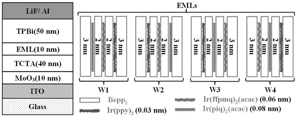
[0068] Prepare white light device W1 according to the above specific embodiment, the device structure is ITO / MoO 3 (3nm) / TCTA(40nm) / Bepp 2 (3nm) / Ir(piq) 2 (acac) (0.08nm) / Bepp 2 (2nm) / Ir(ffpmq) 2 (acac)(0.06nm) / Bepp 2 (2nm) / Ir(ppy) 3 (0.03nm) / Bepp 2 (3nm) / TPBi (50nm) / LiF (1nm) / Al (200nm).

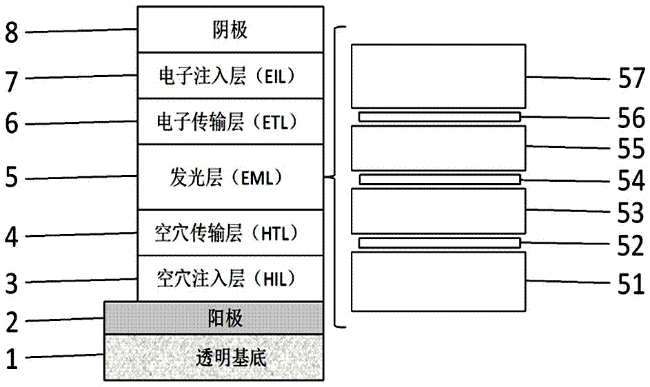
[0069] figure 2 A schematic diagram of the structure of the white light device W1 is given. ITO correspondence figure 1 The middle anode 2 has an area resistance of 15 Ω / □, and the transparent substrate 1 is a transparent glass substrate with a thickness of 1.1mm. MoO 3 correspond figure 1 The hole injection layer 3 has a thickness of 3nm. TCTA correspondence figure 1 The hole transport layer 4 has a thickness of 40nm. TPBi correspondence figure 1 The middle electron transport layer 6 has a thickness of 50nm. LiF correspondence figure 1 The middle electron injection layer 7 has a thickness of 1 nm. Al correspondence figure 1 In the cathode 8, the thickness is 2...

Embodiment 2

[0073] Keep the structure and device preparation materials of the white light device W1 unchanged, and change the ultra-thin red (0.08nm Ir(piq) 2 acac layer), yellow (0.06nm Ir(ffpmq) 2 acac layer), green (0.03nm Ir(ppy) 3 layer) phosphorescent emitting layer embedded in a 10nm thick blue fluorescent emitting layer (Bepp 2 Layer) in the embedding order, the embedding order from the anode to the cathode is green / yellow / red, and the white light device W2 is prepared, and the device structure is ITO / MoO 3 (3nm) / TCTA (40nm) / Bepp 2 (3nm) / Ir(ppy) 3 (0.03nm) / Bepp 2 (2nm) / Ir(ffpmq) 2 acac (0.06nm) / Bepp 2 (2nm) / Ir(piq) 2 acac(0.08nm) / Bepp 2 (3nm) / TPBi (50nm) / LiF (1nm) / Al (200nm), the device structure is as figure 2 shown.


PUM


Abstract

The invention provides a fluorescent / phosphorescent mixed white light OLED of which the light-emitting layer is composed of not less than two fluorescent light-emitting layers formed by the non-doped blue fluorescent material and phosphorescent light-emitting layers which are embedded among the fluorescent light-emitting layers. Any one phosphorescent light-emitting layer is composed of single phosphorescent material of which the thickness is not greater than 0.1nm. The mixed light emitted by different colors of phosphorescent material of all the phosphorescent light-emitting layers is complementary with the blue light emitted by the blue fluorescent material. Different colors of phosphorescent light-emitting layers are separated by 1-3nm blue fluorescent light-emitting material. The total thickness of the light-emitting layers is less than 30nm. Energy transmission between different colors of light-emitting material is changed by changing the order of embedding of the ultrathin phosphorescent light-emitting material in the blue fluorescent light-emitting layers or the thickness of different colors of ultrathin layers so that the emission spectrum of the white light OLED can be easily improved and the relatively ideal white light emission can be acquired.

Description

technical field [0001] The invention belongs to the technical field of organic semiconductor light-emitting devices, and relates to a white light OLED, in particular to a fluorescent / phosphorescent mixed white light OLED. Background technique [0002] Organic light-emitting diodes (Organic light-emitting diodes, OLED) have the characteristics of surface light source, thinness, flexibility, transparency, etc., have been extensively researched and mature, and can be widely used in the field of next-generation lighting and display, with broad market space and Huge application prospects. [0003] The light-emitting layer of a white OLED is usually composed of two or more light-emitting materials with complementary light colors. OLED light-emitting materials are divided into fluorescent materials and phosphorescent materials. [0004] Since only singlet excitons in fluorescent materials can be used to emit light, the internal quantum efficiency of OLEDs based on fluorescent mat...

Claims


Application Information

Patent Timeline
Patent Type & Authority Applications(China)
IPC IPC(8): H01L51/50H01L51/52
CPCH10K50/156H10K50/85H10K50/856H10K2102/301
Inventor 苗艳勤赵波王科翔贾虎生刘旭光高龙王忠强郝玉英王华许并社
Owner TAIYUAN UNIV OF TECH
Learn More