Device for producing oil by carrying out pyrolysis on polystyrene foam plastics

A foam plastic and polystyrene technology, applied in the field of waste recycling, can solve the problems of high quality raw materials, difficulty in continuous feeding, inconvenient transportation, etc., and achieve the effects of easy operation and maintenance, reduced emissions, and reduced production costs

Active Publication Date: 2017-09-12
UNIV OF SCI & TECH BEIJING
View PDF7 Cites 3 Cited by
  • Summary
  • Abstract
  • Description
  • Claims
  • Application Information

AI Technical Summary

Problems solved by technology

[0005] The invention solves the technical problems of traditional polystyrene foam plastics such as inconvenient transportation, low recovery rate, difficulty in continuous feeding, and high quality requirements for raw materials.

Method used


Image

  • Device for producing oil by carrying out pyrolysis on polystyrene foam plastics

Examples


Embodiment 1

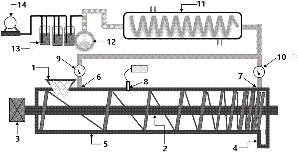
[0032] Styrofoam was treated using the above-mentioned apparatus. The styrofoam was taken from a supermarket bin and had not been washed. The polystyrene foam is put into the reaction device after crushing, and the feed load is 5kg-polystyrene foam / m 3 - barrel volume h. The temperature of the reaction device was controlled at 450°C by an electromagnetic induction thermostat. The residence time of polystyrene foam in the reaction device is 1h. The distance between the detection hole and the feeding port is 1 / 10 of the barrel length, and the distance between the top air guide tube and the feeding port is 1 / 15 of the barrel length. The vacuum in the tip airway circuit is 50 times the vacuum in the terminal airway circuit. Under the above operating conditions of the device, the polystyrene foam cracking rate is 45%, and the concentration of styrene in the condensed crude styrene solution is 65%.

Embodiment 2

[0034] The same device as in Example 1 was used, and the temperature of the reaction device was controlled at 500° C. by an electromagnetic induction thermostat. The residence time of polystyrene foam in the reaction device is 2h. Other conditions are identical with embodiment 1. According to the above operating conditions, the polystyrene foam cracking rate is 75%, and the concentration of styrene in the condensed crude styrene solution is 70%.

Embodiment 3

[0036] The same device as in Example 1 was used, and the temperature of the reaction device was controlled at 550° C. by an electromagnetic induction thermostat. Other conditions are identical with embodiment 2. According to the above operating conditions, the polystyrene foam cracking rate was 90%, and the concentration of styrene in the condensed crude styrene solution was 68%.


PUM


Abstract

The invention relates to a device for producing oil by carrying out pyrolysis on polystyrene foam plastics, belonging to the field of recycling of wastes. When the device is in use, the polystyrene foam plastics enters a screw extrusion device from a feeding port through a stock bin after being coarsely crushed, and heat is generated by means of extrusion and friction strain of a variable pitch screw, so that volume reduction of the polystyrene foam plastics is realized. An electromagnetic induction coil is wound on an external cavity of the outer wall of the device and can be used for enabling the variable pitch screw in the device to become an internal heat source for heating materials by means of self-heating. By adjusting the rotating speed of the screw, the polystyrene foam plastics can be enabled to maintain specific retention time in a specific area so as to be subjected to pyrolysis. Pyrolysis gas is discharged into a condenser pipe from a cavity under the condition of negative pressure and is then liquefied into oil, and exhaust gas of pyrolysis is absorbed by activated carbon, so that secondary pollution is reduced. The front end and the rear end of the device are respectively and externally connected with a vacuum pump, so that negative pressure and an oxygen-free environment are realized in a screw conveying device. The polystyrene foam plastics used by the device does not need to be cleaned, so that the production of cleaning waste water is effective reduced in a recycling process.

Description

technical field [0001] The invention relates to the technical field of waste recycling, in particular to a polystyrene foam pyrolysis oil production device. Background technique [0002] Polystyrene foam has the characteristics of light weight, shock absorption, easy molding, and low price. It is widely used in shockproof packaging of electrical appliances, instruments, handicrafts and fast food packaging. Most of them are disposable and have a large amount of waste. Because polystyrene foam has the characteristics of stable chemical properties, small density, large volume, aging resistance, corrosion resistance, and refractory degradation, it brings increasingly serious pollution to the environment. Although the public's awareness of the pollution caused by polystyrene foam is constantly increasing, because it greatly facilitates people's daily life, and the technology of corresponding substitutes is not yet mature, it is believed that it will continue to be used for a per...

Claims


Application Information

Patent Timeline
Patent Type & Authority Applications(China)
IPC IPC(8): C10G1/10C10B57/00
CPCC10B57/00C10G1/10C10G2300/1003
Inventor 吴川福马欣欣王晓娜周继夏德宏夏菲洋高明汪群慧
Owner UNIV OF SCI & TECH BEIJING
Why Eureka
Try Eureka