Purification device for industrial waste gases

A technology for purifying equipment and industrial waste gas, which is applied in the directions of gas treatment, air quality improvement, chemical instruments and methods, etc. It can solve problems such as difficult treatment of volatile organic compound equipment, achieve simple structure, save water resources, and reduce use costs Effect

Inactive Publication Date: 2017-09-15
弘毅天承知识产权股份有限公司
View PDF0 Cites 14 Cited by
  • Summary
  • Abstract
  • Description
  • Claims
  • Application Information

AI Technical Summary

Problems solved by technology

[0004] The purpose of the present invention is: in order to solve the technical problem that the existing equipment is difficult to deal with the volatile organic compounds and peculiar smell in the waste gas, the present invention provides a kind of purification equipment for industrial waste gas

Method used


Image

  • Purification device for industrial waste gases
  • Purification device for industrial waste gases
  • Purification device for industrial waste gases

Examples


Embodiment 1

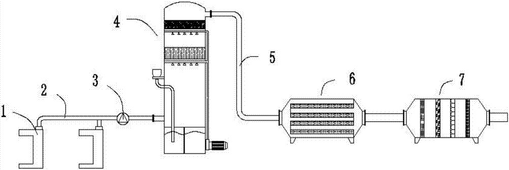
[0023] Such as Figures 1 to 4 As shown, the present embodiment provides a purification device for industrial waste gas, including a main exhaust gas pipeline 2, and an exhaust fan 3 is arranged on the main exhaust gas pipeline 2, and it is characterized in that one end of the main exhaust gas pipeline 2 is connected with a water tank located in a spraying workshop. The curtain cabinet 1, the other end of the waste gas main pipeline 2 is connected with a circulation absorption tower 4, and the circulation absorption tower 4 is connected with an activated carbon adsorber 6 and a strengthened absorber 7 in turn through a pipeline A5, and the strengthened absorber 7 includes a shell 7- 6. The two ends of the housing 7-6 are respectively provided with an air inlet 7-1 and an air outlet 7-7, and the housing 7-6 is detachably provided with a coarse filter cotton layer 7-2 and a HEPA filter layer 7- 3. The photocatalytic filter plate 7-4 and nano photocatalytic filter plate 7-5, the ...

Embodiment 2

[0027] This embodiment is further optimized on the basis of embodiment 1, specifically:

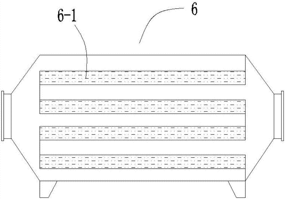
[0028] The activated carbon adsorber 6 is provided with a plurality of activated carbon adsorption layers 6-1, and the distance between two adjacent activated carbon adsorption layers 6-1 is equal.

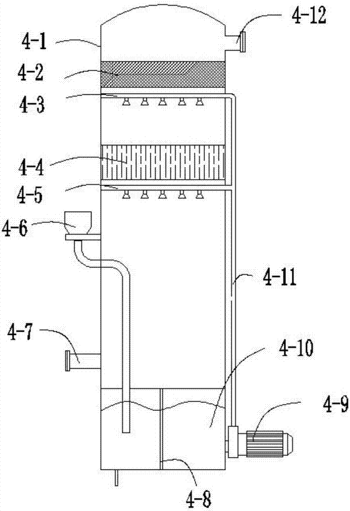
[0029] The circulation absorption tower 4 comprises a tower body 4-1, an air inlet pipe 4-7 and an outlet pipe 4-12 communicated with the inside of the tower body 4-1, and the tower body 4-1 is sequentially provided with dewatering pipes from top to bottom. The mist device 4-2, the packing layer 4-4, and the tower body 4-1 are also equipped with a circulating spraying system.

[0030] The circulating spray system includes a water tank 4-10 arranged at the inner bottom of the tower body 4-1 and a main spray pipe 4-11 arranged on the outer wall of the tower body 4-1, and the main spray pipe 4-11 passes through the water pump 4-9 Connected with the water tank 4-10, the circulating spray system ...

Embodiment 3

[0032] This embodiment is further optimized on the basis of embodiment 1 or 2, specifically:

[0033] One side of the tower body 4-1 is provided with a water inlet 4-6 communicating with the water tank 4-10, a liquid level sensor 4-8 is provided in the water tank 4-10, and a sewage outlet is provided at the bottom of the water tank 4-10.


PUM


Abstract

The invention discloses a purification device for industrial waste gases, and relates to the field of waste gas purification equipment, the purification device includes a waste gas main pipeline, the waste gas main pipeline is provided with an exhaust fan, one end of the waste gas main pipeline is connected with a water screen cabinet located in a spraying workshop, the other end of the waste gas main pipeline is connected with a circulating absorption tower, the circulating absorption tower is sequentially connected with an activated carbon adsorber and a strengthening adsorber by a pipeline A, the strengthening adsorber comprises a casing, two ends of the casing are respectively provided with a gas inlet and a gas outlet, the casing is internally detachably in turn provided with a coarse filter cotton layer, a HEPA filter layer, a photocatalytic filter plate and a nano photocatalytic filter plate, and the coarse filter cotton layer is close to the gas inlet. The purification device is simple in structure, after absorption and filtering by the heavy water curtain cabinet, the circulation absorption tower and the activated carbon adsorber, large and small dust particles in the waste gases are basically sedimentated, and volatile organic compounds and odor gases are absorbed by the strengthening adsorber so as to achieve the advantage of up-to-standard emission.

Description

technical field [0001] The invention relates to the field of waste gas purification equipment, and more specifically relates to a purification equipment for industrial waste gas. Background technique [0002] Industrial waste gas refers to the general term for all kinds of pollutant gases that are discharged into the air during fuel combustion and production processes in the factory area. These exhaust gases include: carbon dioxide, carbon disulfide, hydrogen sulfide, fluoride, nitrogen oxides, chlorine, hydrogen chloride, carbon monoxide, sulfuric acid mist lead mercury, beryllium compounds, smoke and productive dust, which will pollute the air when discharged into the atmosphere. These substances enter the human body through the respiratory tract in different ways, some directly cause harm, and some have a cumulative effect, which will seriously endanger human health. Different substances will have different effects. [0003] Therefore, industrial waste gas cannot be dir...

Claims


Application Information

Patent Timeline
Patent Type & Authority Applications(China)
IPC IPC(8): B01D53/86B01D50/00
CPCB01D53/007B01D53/02B01D53/1487B01D53/86B01D2255/802B01D2257/90B01D2258/06B01D2253/102B01D50/60Y02A50/20
Inventor 樊明伟
Owner 弘毅天承知识产权股份有限公司
Why Eureka
Try Eureka