Microwave photonic zero-intermediate-frequency receiving device and method

A receiving device and microwave photon technology, applied in the field of microwave technology and optical communication, can solve the problems of few microwave photon zero-IF receiving technology, complex structure, difficult to suppress image interference, etc.

Active Publication Date: 2017-09-15
XIDIAN UNIV
View PDF3 Cites 25 Cited by
  • Summary
  • Abstract
  • Description
  • Claims
  • Application Information

AI Technical Summary

Problems solved by technology

This structure has the following disadvantages: (1) When the frequency of the RF signal is high, one or two stages of down-conversion are often required. After each stage of frequency conversion, it is generally necessary to use a band-pass filter to filter out the down-converted intermediate frequency signal for post-processing. The structure is complex; (2) In the process of down-converting to intermediate frequency signals, image interference is difficu

Method used


Image

  • Microwave photonic zero-intermediate-frequency receiving device and method
  • Microwave photonic zero-intermediate-frequency receiving device and method
  • Microwave photonic zero-intermediate-frequency receiving device and method

Examples


Embodiment Construction

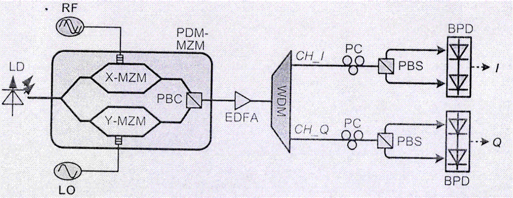
[0022] The embodiments of the present invention are described in detail below in conjunction with the accompanying drawings: this embodiment is implemented on the premise of the technical solution of the present invention, and detailed implementation methods and specific operating procedures are provided, but the protection scope of the present invention is not limited to the following The described embodiment:

[0023] In this example, the device includes LD, two radio frequency signal sources, PDM-MZM, EDFA, WDM, PC, PBS and BPD. The output port of the LD is connected to the optical input port of the modulator, and the output ports of the two RF signal sources are respectively connected to the two RF input ports of the modulator. The modulator is connected to the EDFA, and the EDFA is connected to the WDM common port. Connect PC, PBS and BPD respectively.

[0024] In this example, the specific implementation steps of the method are:

[0025] Step 1: The LD generates a cont...


PUM


Abstract

The invention discloses a microwave photonic zero-intermediate-frequency receiving device and method. The method relates to the technical field of microwave and the technical field of optical communication. The method is as shown in the drawings. The device comprises a laser (LD), a polarization multiplexing Mach-Zehnder modulator (PDM-MZM), an erbium-doped optical fibre amplifier (EDFA), a wavelength division multiplexer (WDM), polarization controllers (PCs), a polarization beam splitter (PBS) and balance photoelectric detectors (BPDs). Modulation and polarization multiplexing of radio-frequency (RF) and local oscillator (LO) signals are carried out by utilization of the PDM-MZM; the WDM separates upper and lower optical sidebands; the PCs are respectively utilized for adjusting the polarization states of optical signals; and finally, the two BPDs respectively output I-channel and Q-channel baseband signals. By means of the microwave photonic zero-intermediate-frequency receiving device and method disclosed by the invention, zero-intermediate-frequency receiving is realized through a photonic method; the electronic bottleneck in the traditional electric field technology can be overcome; and the microwave photonic zero-intermediate-frequency receiving device has the advantages of being wide in working band, high in IQ balance degree, inhibited in direct-current offset and even-order distortion, electromagnetic-interference-resistant and the like.

Description

technical field [0001] The invention relates to the field of microwave technology and the field of optical communication technology, and mainly relates to the realization of zero-IF reception of broadband microwave vector signals through microwave photon technology. Background technique [0002] As people's requirements for communication rates are getting higher and higher, electronic communication systems are now developing in the direction of high-frequency bands and large bandwidths. In the traditional signal processing technology based on electronics, there are speed bottlenecks in electronic devices, large timing jitter, and serious electromagnetic interference. Photonics signal processing technology has a series of advantages such as simplicity, portability, wide bandwidth, and anti-electromagnetic interference, and has attracted much attention. [0003] Most of the current electronic systems use a superheterodyne receiver architecture. The microwave vector signal rec...

Claims


Application Information

Patent Timeline
IPC IPC(8): H04B10/50H04B10/516H04B10/61H04B10/67H04J14/02H04J14/06
Inventor 高永胜文爱军谭庆贵
Owner XIDIAN UNIV
Why Eureka
Try Eureka