
Waste gas photolysis treatment device

A treatment device and photolysis technology, applied in gas treatment, separation methods, and separation of dispersed particles, can solve the problems of inability to process long molecular chain organic matter and benzene series, low efficiency of organic waste gas treatment, and low removal rate of organic matter. Achieve long-term stable treatment effect, high waste gas conversion efficiency and simple structure

Pending Publication Date: 2017-10-03
HONGAN FANGDA ENVIRONMENTAL PROTECTION ENG
View PDF1 Cites 1 Cited by
  • Summary
  • Abstract
  • Description
  • Claims
  • Application Information

AI Technical Summary

Problems solved by technology

At present, the treatment methods of organic waste gas have the problems of high particle concentration leading to blockage of treatment devices, insufficient degradation time leading to partial degradation, and inability to deal with long molecular chain organics and benzene series. Therefore, the treatment methods of organic waste gas in the prior art cannot Complete treatment of organic waste gas, low treatment efficiency
It is a common way to treat industrial organic waste gas by photolysis purification, but the existing photolysis purification device has a relatively simple treatment method for industrial organic waste gas, and the removal rate of organic matter in the waste gas is not high, and the tail gas after treatment There will still be the problem of secondary pollution, which makes the treatment efficiency of organic waste gas low and the treatment effect poor

Method used


Image

  • Waste gas photolysis treatment device

Examples


Embodiment Construction

[0018] The specific implementation of the present invention will be described in detail below in conjunction with the accompanying drawings. As a part of this specification, the principles of the present invention will be described through examples. Other aspects, features and advantages of the present invention will become clear through the detailed description. In the referenced drawings, the same reference numerals are used for the same or similar components in different drawings.

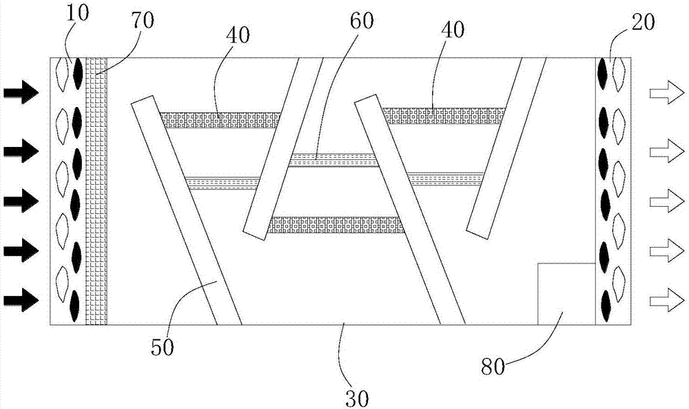
[0019] Such as figure 1 As shown, it is a schematic structural diagram of a waste gas photolysis treatment device in a preferred embodiment of the present invention. The chemical organic substances treated by photolysis in the present invention include benzenes, alkanes, aromatic hydrocarbons, olefins, alcohols, ketones, Aldehydes, esters, etc. At the same time, the invention has deodorizing and sterilizing functions, and can be used for biological odor and bacterial disinfection treatment. The ...


PUM


Abstract

The invention discloses a waste gas photolysis treatment device, which comprises an inlet separation layer and an outlet separation layer, wherein a sealed photolysis reaction region is defined between the inlet separation layer and the outlet separation layer; a high-energy ultraviolet lamp is arranged in the photolysis reaction region; a gas detector is arranged in the photolysis reaction region; the gas detector is near the outlet separation layer; the waste gas photolysis treatment device also comprises a controller; the high-energy ultraviolet lamp and the gas detector are respectively and electrically connected with the controller. The waste gas photolysis treatment device disclosed by the invention has the advantages that the structure is simple; the design is reasonable; the photolysis mode is used for treating organic waste gas; no high temperature and high pressure risk exists; the use is safe; the operation is simple; the high-energy ultraviolet lamp is used; ultraviolet rays with specific wavelength are used for converting the organic matters; the conditions that active carbon reaches saturation through adsorption, and the effect reduction occurs cannot occur; the waste gas conversion efficiency is high; the long-period and stable treatment effect is achieved. By the multi-stage passage structure design mode, the condition that the waste gas is not fully degraded is effectively avoided; the effect of thorough waste gas treatment is achieved.

Description

technical field [0001] The invention relates to the technical field of organic waste gas purification, in particular to a waste gas photolysis treatment device. Background technique [0002] Organic waste gas treatment refers to the treatment of adsorption, filtration and purification of organic waste gas generated in the process of industrial production. Usually, organic waste gas treatment includes formaldehyde organic waste gas treatment, benzene, toluene, xylene and other benzene series organic waste gas treatment, acetone butanone organic Waste gas treatment, ethyl acetate waste gas treatment and oil mist organic waste gas treatment. The characteristics of organic waste gas treatment are: organic waste gas is generally flammable, explosive, toxic and harmful, insoluble in water, soluble in organic solvents, and difficult to treat. The organic waste gas condensation recovery method, adsorption method, direct combustion method, absorption method and biodegradation method...

Claims


Application Information

Patent Timeline
IPC IPC(8): B01D53/76B01D53/72
CPCB01D53/007B01D53/72B01D53/76B01D2259/804
Inventor 万伟万家学
Owner HONGAN FANGDA ENVIRONMENTAL PROTECTION ENG
Learn More