Single-step pulse laser polishing method for metal surfaces

A pulsed laser and metal surface technology, applied in laser welding equipment, metal processing equipment, welding equipment, etc., can solve the problems of not achieving polished surface performance and small penetration depth

Inactive Publication Date: 2017-10-03
BEIHANG UNIV
View PDF3 Cites 23 Cited by
  • Summary
  • Abstract
  • Description
  • Claims
  • Application Information

AI Technical Summary

Problems solved by technology

Most of the existing laser polishing technologies only consider the influence of the surface morphology of the material (for example, the laser fine polishing process with a pulse width of less than 50ns does not have a large penetration depth on the material surface), or the laser polishing process

Method used


Image

  • Single-step pulse laser polishing method for metal surfaces
  • Single-step pulse laser polishing method for metal surfaces
  • Single-step pulse laser polishing method for metal surfaces

Examples


Embodiment 1

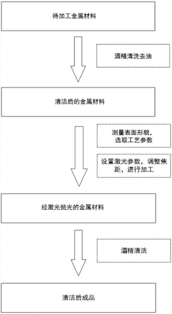
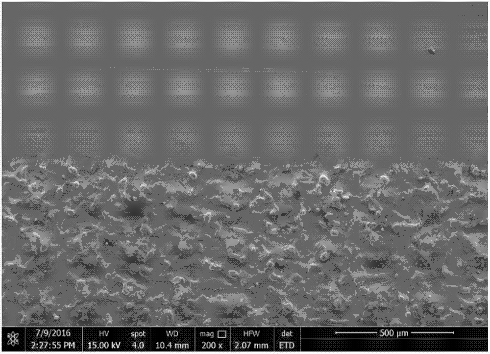
[0043] (1): Take a TC4 titanium alloy block with a surface roughness of about 5 μm, and simply clean and degrease the surface.

[0044] (2): Use a three-dimensional profiler to measure the surface to be polished.

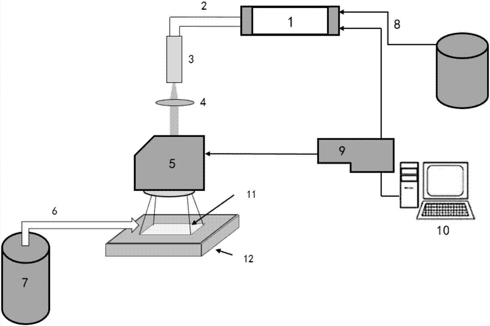
[0045] (3): Put the sample in such as figure 2 On the workbench of the nanosecond laser processing system of SPI company shown (using a fiber laser with a wavelength of 1060nm), set the laser power to 20W, set the pulse width to 200ns, the frequency to 500kHz, the scanning speed to 200mm / s, and set the scanning area The size is 50mm×50mm, the spot scanning overlap rate is 50%, the inert gas is turned on to protect the processing surface, and the laser processing system is started to start processing. (4): Remove the processed titanium alloy block from the workbench and wipe it with absolute alcohol.

[0046] Such as image 3Shown is the electron micrograph of the laser polished and unpolished area boundary of the TC4 titanium alloy surface obtained after process...

Embodiment 2

[0048] (1): Take a copper alloy block with a surface roughness of about 20 μm, and simply clean and degrease the surface.

[0049] (2): Use a three-dimensional profiler to measure the surface to be polished.

[0050] (3): Put the sample in such as figure 2 On the workbench of the high-power laser processing system of SPI Company (using a fiber laser with a wavelength of 1060nm) shown, set the laser power to 100W, set the pulse width to 50μs, the frequency to 1kHz, and the scanning speed to 500mm / s, and set the scanning area The size is 50mm×50mm, the spot scanning overlap rate is 30%, the inert gas is turned on to protect the processing surface, and the laser processing system is started to start processing.

[0051] (3): Remove the processed steel block from the workbench and wipe it with absolute alcohol.

Embodiment 3

[0053] (1): Take a steel block with a surface roughness of about 1 μm, and simply clean and degrease the surface.

[0054] (2): Use a three-dimensional profiler to measure the surface to be polished.

[0055] (3): Put the sample in such as figure 2 On the workbench of the nanosecond laser processing system of SPI Company (using a fiber laser with a wavelength of 1060nm) shown, set the laser power to 20W, set the pulse width to 50ns, the frequency to 1MHz, and the scanning speed to 2000mm / s, and set the scanning area The size is 50mm×50mm, the spot scanning overlap rate is 70%, the inert gas is turned on to protect the processing surface, and the laser processing system is started to start processing.

[0056] (3): Remove the processed steel block from the workbench and wipe it with absolute alcohol.


PUM

PropertyMeasurementUnit
Surface roughnessaaaaaaaaaa

Abstract

The present invention is a single-step pulse laser polishing method for metal surfaces: 1. Simply clean and degrease the surface of the metal material to be processed. 2. Use a three-dimensional profiler to measure the surface to be polished. 3. Place the metal material to be processed on the workbench of the laser processing system, set the laser parameters, start the laser processing system, use the galvanometer to scan the laser at a certain speed and path on the surface of the metal material, and finally obtain remelting on the surface Layer, inert gas is used for protection during processing. 4. Simple cleaning of processed metal materials. Compared with traditional metal surface polishing methods such as mechanical polishing and chemical/electrochemical polishing, the present invention uses laser heating and melting to form a molten pool under the multi-directional action of surface tension and gravity, and the molten material in the molten pool will be redistributed through flow. Around the initial position, the peak-to-valley height difference of most rough surfaces is reduced after rapid solidification, thereby obtaining a polishing effect on the rough surface.

Description

technical field [0001] The invention relates to a single-step pulse laser polishing method for metal surfaces. The method can be widely applied to the surface polishing of metal parts, and a smooth and smooth metal surface can be quickly obtained by using laser treatment, which belongs to the technical field of laser treatment of metal material surfaces. Background technique [0002] At present, the commonly used techniques for surface polishing of metal materials mainly include mechanical polishing and chemical / electrochemical polishing. Among them, automated polishing technologies, such as electropolishing, electrochemical polishing, grinding, etc., have many disadvantages, such as rounded corners, which cannot process deeper areas of complex components, for non-flat surfaces and metal components with corners It is not applicable. If you use a precision CNC grinding machine, you will face programming difficulties and cannot perform differential polishing on different area...

Claims


Application Information

Patent Timeline
IPC IPC(8): B23K26/352
CPCB23K26/352
Inventor 管迎春马程鹏
Owner BEIHANG UNIV
Why Eureka
Try Eureka