Barrel-shaped non-running-on spring and mixed density medium side-placed type vibromill

A technology of mixed density and vibration grinding, applied in grain processing and other directions, can solve the problems of high noise and low efficiency, and achieve the effects of high energy consumption, reduced energy consumption and convenient maintenance.

Inactive Publication Date: 2017-10-13
NANJING INST OF TECH
View PDF11 Cites 0 Cited by
  • Summary
  • Abstract
  • Description
  • Claims
  • Application Information

AI Technical Summary

Problems solved by technology

[0006] The invention provides a side-mounted vibrating mill with a convex non-coil spring and a mixed density medium, which has a side-mounted structure and technical features in which the vibrator, that is, the vibration motor, is located on the left or right side of the grinding cylinder. The upper mass and the spring form a vibration system, the spring is a convex type non-coil spring with variable stiffness; in order to further increase the impact, extrusion, shearing, and collision energy of the grinding ball in the cylinder during relative motion, the optimal setting of the mixed density medium ratio is implemented, which is consistent with the current Compared with the widely used ordinary side-mounted vibration mill system, it has the characteristics of high efficiency and low noise, and aims to effectively solve the technical bottleneck problems of high noise and low efficiency that have been pending for the existing vibration mill.

Method used


Image

  • Barrel-shaped non-running-on spring and mixed density medium side-placed type vibromill
  • Barrel-shaped non-running-on spring and mixed density medium side-placed type vibromill
  • Barrel-shaped non-running-on spring and mixed density medium side-placed type vibromill

Examples


Embodiment Construction

[0027] In order to deepen the understanding of the present invention, the present invention will be described in further detail below in conjunction with the accompanying drawings and embodiments, which are only used to explain the present invention and do not limit the protection scope of the present invention.

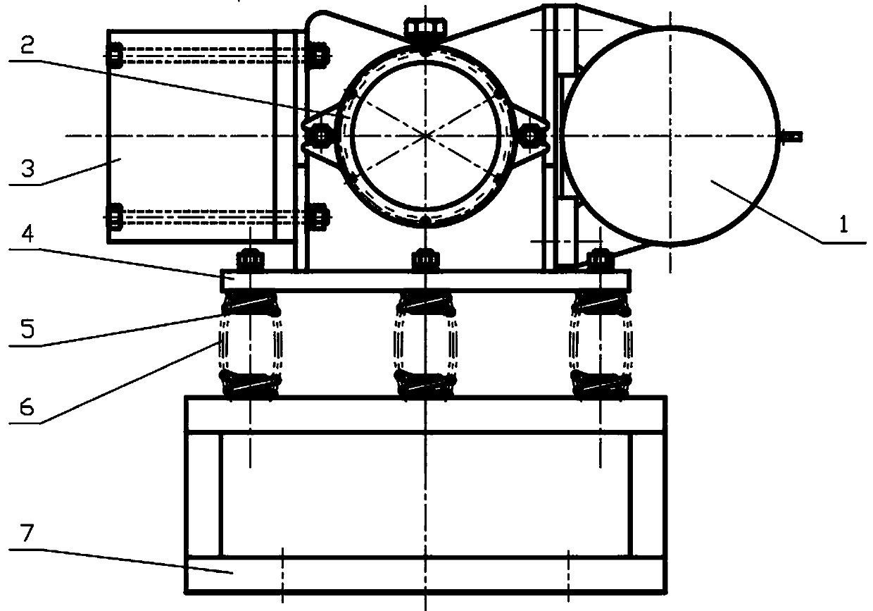
[0028] figure 1Shown is a schematic structural diagram of the vibration mill of the present invention. The mill mainly consists of a vibration motor 1 , a grinding cylinder 2 , a counterweight 3 , an upper body frame 4 , a spring guide post 5 , a spring group 6 and a base 7 . The filling factor of the grinding media in the cylinder can be set to 70%. The grinding media are wear-resistant steel balls and tungsten steel balls. The ratio of the two types of grinding media is 6:4. mm, the material is ultra-hard fine powder, the vibration frequency of the mill is 1450 rpm, the measured amplitude is <22mm, and the vibration intensity is <20.

[0029] like figure 1 As sho...


PUM


Abstract

The invention discloses a barrel-shaped non-running-on spring and mixed density medium side-placed type vibromill. The vibromill comprises a main vibration system. The main vibration system comprises a vibration motor which is controlled through a frequency converter and used as a vibration source, at least one milling barrel connected with the vibration motor, and a counter weight body which is in flange connection with the milling barrel. The vibration motor, the milling barrel and an upper medium body frame form an upper medium body. The upper medium body is connected with a base through a spring set. The spring set is composed of a plurality of barrel-shaped non-running-on coil springs. Each spring is formed by coiling a steel wire. Each steel wire is coiled into a barrel-shaped coil structure. Each barrel-shaped non-running-on coil spring comprises at least four circles of effective screws. The vibromill has the positive, obvious and unique effects and the characteristics of particle refining, deaggregating, low energy consumption, high powder milling efficiency and energy utilization rate, effective energy accumulation, energy conservation, stable operation, remarkable noise reduction, good vibration isolation effect and the like.

Description

technical field [0001] The invention relates to a grinding equipment for vibration preparation of superfine powder of materials, which is a side-mounted vibrating mill with a convex non-coil spring and a medium with a mixed density ratio, belonging to vibration utilization and powder engineering interdisciplinary science and technology. Background technique [0002] Vibrating mill is a vibrating mechanical equipment that uses the principle of vibration to complete the ultrafine grinding operation of materials. In the existing ultrafine powder preparation technology, vibrating mill and other preparation methods include gas phase synthesis, liquid phase synthesis, jet milling, Compared with the drum milling method, it has the advantages of high mechanical activity of the material, convenient purification, low cost, simple structure, and high efficiency. The existing vibrating mill support spring generally adopts a linear equal-pitch helical spring; its medium generally adopts ...

Claims


Application Information

Patent Timeline
IPC IPC(8): B02C19/16
CPCB02C19/16
Inventor 杨小兰曾琴刘极峰胡廷杰
Owner NANJING INST OF TECH
Why Eureka
Try Eureka