Explosion-proof incineration treatment system for solid waste
A technology for disposal system, solid waste
- Summary
- Abstract
- Description
- Claims
- Application Information
AI Technical Summary
Problems solved by technology
Method used
Image
Examples
Embodiment 1
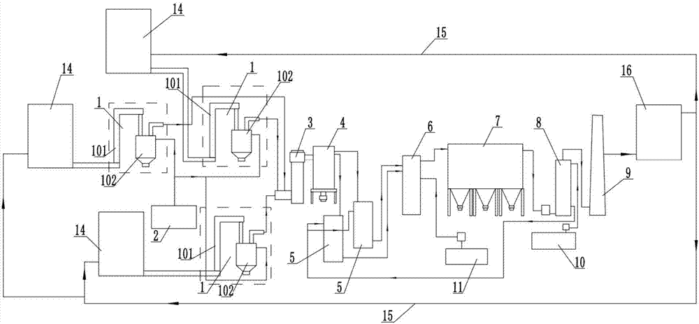
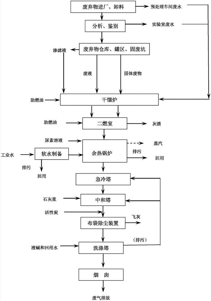
[0032] Embodiment 1: as figure 1 As shown, the solid waste explosion-proof incineration disposal system of this embodiment includes a solid waste crushing device 14, a waste feeding device 13, a dry distillation device 1, a secondary combustion chamber 3, a waste heat boiler 4, a quench tower 5, a neutralization Tower 6, bag dust removal device 7, washing tower 8 and chimney 9, retort furnace 1 and waste heat boiler 4 are all connected to softening water device 2, washing tower 8 is connected to lye pool 10, neutralization tower 6 is connected to lime slurry pool 11, and chimney The smoke outlet of 9 is connected to one input end of the mixing device 16, the other input end of the mixing device 16 is connected to the nitrogen storage tank 17, and the output end of the mixing device 16 is connected to the solid waste crushing device 14 through the smoke return pipe 15. The solid waste disposal process of the present invention includes the pulverization process of solid waste pa...
Embodiment 2
[0034] Embodiment 2: This embodiment has been improved on the basis of Embodiment 1, and the washing tower 8 is connected with the quenching tower 5 through pipelines, and the residual lye, salt, etc. of the washing tower 8 are transported to the quenching tower 5 by delivery equipment . The treatment process of this embodiment also includes a semi-dry deacidification process and a wet deacidification process. The semi-dry deacidification process includes introducing the lime slurry in the lime slurry pool 11 into the neutralization tower 6 to mix with the acid gas in the flue gas. The reaction process of wet deacidification includes and the reaction process of passing the lye in the lye pool 10 into the scrubber and the acid gas in the flue gas; The lye and the salt produced are introduced into the quench tower 5. Since the residual lye is introduced into the quenching tower 5, on the one hand, it is used to enhance the quenching effect of the quenching tower 5, and on the o...
Embodiment 3
[0035] Embodiment 3: This embodiment is further improved on the basis of Embodiment 2. Two sets of quenching towers 5 are arranged. The work can be switched among the towers 5 to realize one for use and one for standby. Since the residual lye and salt in the washing tower 8 are introduced into the quenching tower 5, the salt content in the quenching tower 5 increases. In order not to affect the work effect, the quenching tower 5 needs to be desalted regularly, and the desalination needs to be shut down. Therefore, two sets of quenching towers 5 are used for switching to realize continuous operation. The treatment process of this embodiment includes a semi-dry deacidification process and a wet deacidification process. The semi-dry deacidification process includes introducing the lime slurry in the lime slurry pool 11 into the neutralization tower 6 and the acid gas in the flue gas. The reaction process, wet deacidification includes and the reaction process of passing the lye i...
PUM
 Abstract
Description
Claims
Application Information
 - R&D
- Intellectual Property
- Life Sciences
- Materials
- Tech Scout
- Unparalleled Data Quality
- Higher Quality Content
- 60% Fewer Hallucinations
Browse by: Latest US Patents, China's latest patents, Technical Efficacy Thesaurus, Application Domain, Technology Topic, Popular Technical Reports.
© 2025 PatSnap. All rights reserved.Legal|Privacy policy|Modern Slavery Act Transparency Statement|Sitemap|About US| Contact US: help@patsnap.com


