Water spraying type internal combustion engine exhaust system

A technology of exhaust system and internal combustion engine, which is applied to internal combustion piston engines, exhaust devices, combustion engines, etc., can solve the problems of high soot emission, low combustion efficiency, and large diameter of gas soot particles, and achieve the goal of suppressing NOx The effect of generating, improving working ability, and improving service life

Inactive Publication Date: 2017-10-24
HARBIN INST OF TECH
View PDF5 Cites 4 Cited by
  • Summary
  • Abstract
  • Description
  • Claims
  • Application Information

AI Technical Summary

Problems solved by technology

[0007] The invention aims to solve the problems of large gas soot particle diameter, high soot emission and low combustion efficiency in the existing internal combustion engine exhaust system, and further provides a water spray type internal combustion engine exhaust system

Method used


Image

  • Water spraying type internal combustion engine exhaust system

Examples


specific Embodiment approach 1

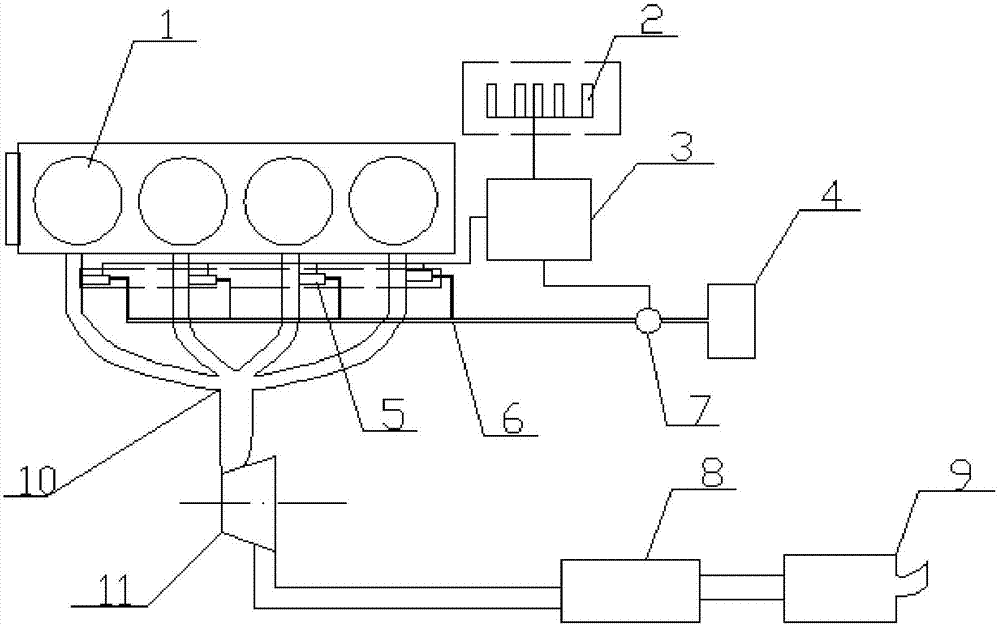
[0020] Specific implementation manner one: such as figure 1 As shown, the water injection type internal combustion engine exhaust system of this embodiment includes an internal combustion engine combustion chamber 1, a signal sensor 2, a control unit 3, a water injection device, an exhaust gas catalytic device 8, a muffler device 9, an exhaust gas manifold 10, and a turbo booster. Pressure device 11; the water spray device includes a water tank 4, a water pipe 6, a water pump 7, and a plurality of water spray nozzles 5. The number of water spray nozzles 5 is set in accordance with the number of exhaust branch pipes of the combustion chamber 1 of the internal combustion engine. Each exhaust branch pipe is provided with a water spray nozzle 5, one end of the exhaust branch pipe is connected with the corresponding combustion chamber, the other end of the exhaust branch pipe is connected with the exhaust gas main pipe 10, and each water spray nozzle 5 is connected with The water pi...

specific Embodiment approach 2

[0022] Specific implementation manner two: such as figure 1 As shown, the number of water spray nozzles 5 in this embodiment is four. With this design, the number of water spray nozzles 5 is set corresponding to the number of exhaust branch pipes, and the control unit 3 controls the water spray device to inject an appropriate amount of atomized water into each exhaust branch pipe in a timely manner by processing engine signals. The other components and connection relationships are the same as in the first embodiment.

specific Embodiment approach 3

[0023] Specific implementation manner three: such as figure 1 As shown, the water spray nozzle 5 of this embodiment is connected to the corresponding exhaust branch pipe by threads, and the water spray nozzle 5 is an electronically controlled spray nozzle. With such a design, the control unit 3 controls the water spray device to inject an appropriate amount of atomized water into each exhaust branch pipe in a timely manner by processing the engine signal. Other components and connection relationships are the same as those in the first or second embodiment.


PUM


Abstract

The invention relates to an internal combustion engine exhaust system, in particular to a water spraying type internal combustion engine exhaust system. The water spraying type internal combustion engine exhaust system solves the problems that in an existing internal combustion engine exhaust system, the diameter of gas soot particles is large, the soot discharge quantity is high, and the combustion efficiency is low. The number of water spraying nozzles is consistent with that of exhaust branch pipes of an internal combustion engine combustion chamber. Each exhaust branch pipe of the internal combustion engine combustion chamber is provided with the corresponding water spraying nozzle. One end of each exhaust branch pipe communicates with a corresponding combustion chamber body. The other ends of the exhaust branch pipes communicate with a tail gas exhaust manifold. Each water spraying nozzle communicates with a water pipe through a pipeline. The water pipe is connected with a water tank through a water pump. A control unit is connected with the water pump and the multiple water spraying nozzles. A signal sensor is electrically connected with the control unit. An exhaust opening of the tail gas exhaust manifold sequentially communicates with a tail gas catalysis device and a noise elimination device through a turbocharging device. The water spraying type internal combustion engine exhaust system is used on an internal combustion locomotive.

Description

Technical field [0001] The invention relates to an internal combustion engine exhaust system, in particular to a water injection type internal combustion engine exhaust system, and belongs to the field of diesel locomotives. Background technique [0002] The main components of the current exhaust system of internal combustion engines are turbochargers and catalytic converters. For diesel engines, soot particles in the exhaust gas are important pollutant emissions. The emission control of soot is mainly through the capture and reburning of particulates by particulate traps, but the particulate traps face a large local thermal load. Pore ​​clogging, catalyst poisoning and other issues have greatly reduced the service life and working efficiency of the particulate trap. [0003] Because the high-temperature gas directly contacts the exhaust pipe and turbine blades without cooling measures, the exhaust pipe and turbine blades face extremely high thermal load, which will affect their s...

Claims


Application Information

Patent Timeline
Patent Type & Authority Applications(China)
IPC IPC(8): F02B41/02F01N3/04
CPCF01N3/04F02B41/02Y02T10/12
Inventor 周伟星吴传伟
Owner HARBIN INST OF TECH
Why Eureka
Try Eureka