Multi-purpose electromagnetic induction melting device and method

A technology of electromagnetic induction and electromagnetic induction coil, which is applied in the field of multi-purpose electromagnetic induction smelting equipment, can solve the problems of complex structure, easy to be oxidized, and exposed electromagnetic induction coil, achieve high airtight effect, prevent oxidation or corrosion, and improve pouring accuracy Effect

Inactive Publication Date: 2017-11-24
XI AN JIAOTONG UNIV
View PDF10 Cites 13 Cited by
  • Summary
  • Abstract
  • Description
  • Claims
  • Application Information

AI Technical Summary

Problems solved by technology

However, the use requirements of each melting furnace are different, and it cannot be guaranteed that it can be used in an oxidizing or corrosive environment, or it cannot melt materials with extremely poor magnetic permeability, or it cannot control parameters such as the diameter of the liquid column or the discharge volume when the molten material is discharged.
[0004] For example, Chinese patent application CN 201020592296 discloses an electromagnetic induction melting furnace, which includes a furnace shell, a crucible, and a heating assembly composed of a thermal insulation layer and an electromagnetic induction coil. Although it has high heating efficiency and is easy to maintain, it cannot The magnetically conductive material is heated, and the electromagnetic induction coil is exposed, which is easily oxidized during use, and cannot meet the requirements of high-temperature molten liquid being discharged accurately at the bottom
[0005] For example, Chinese patent application CN 201320039078 discloses an anhydrous cooling induction heating smelting furnace. In the induction heating smelting furnace, a furnace lining composed of an inner refractory material and an outer refractory material is arranged between the electromagnetic induction coil and the crucible, and the The thermal insulation layer, by reducing the heat radiation and heat conduction of the furnace lining to the electromagnetic induction coil, ensures that the electromagnetic induction coil works at a lower temperature, thereby saving the cooling of the electromagnetic induction coil; but this melting furnace is also not available Due to the heating of non-magnetic materials, and the electromagnetic induction coil is exposed, it is very easy to be oxidized during use, and it cannot meet the requirements of accurate discharge of high-temperature melt at the bottom
[0006] Another example is Chinese patent application CN 201610144810, which discloses a jet-type induction melting furnace, which uses an electromagnetic induction body to achieve melting of magnetically conductive and non-magnetically conductive materials, but since the device does not protect the electromagnetic induction coil, It cannot be used in an oxygen environment or a corrosive environment. In addition, because the device uses multi-layer insulation materials, and is equipped with a blowing system and a mechanical stirring system, the structure is extremely complicated, installation and maintenance are extremely inconvenient, and the melting of the melt cannot be achieved. pouring operation

Method used


Image

  • Multi-purpose electromagnetic induction melting device and method

Examples


Embodiment Construction

[0026] Below in conjunction with accompanying drawing and specific embodiment the present invention is described in detail:

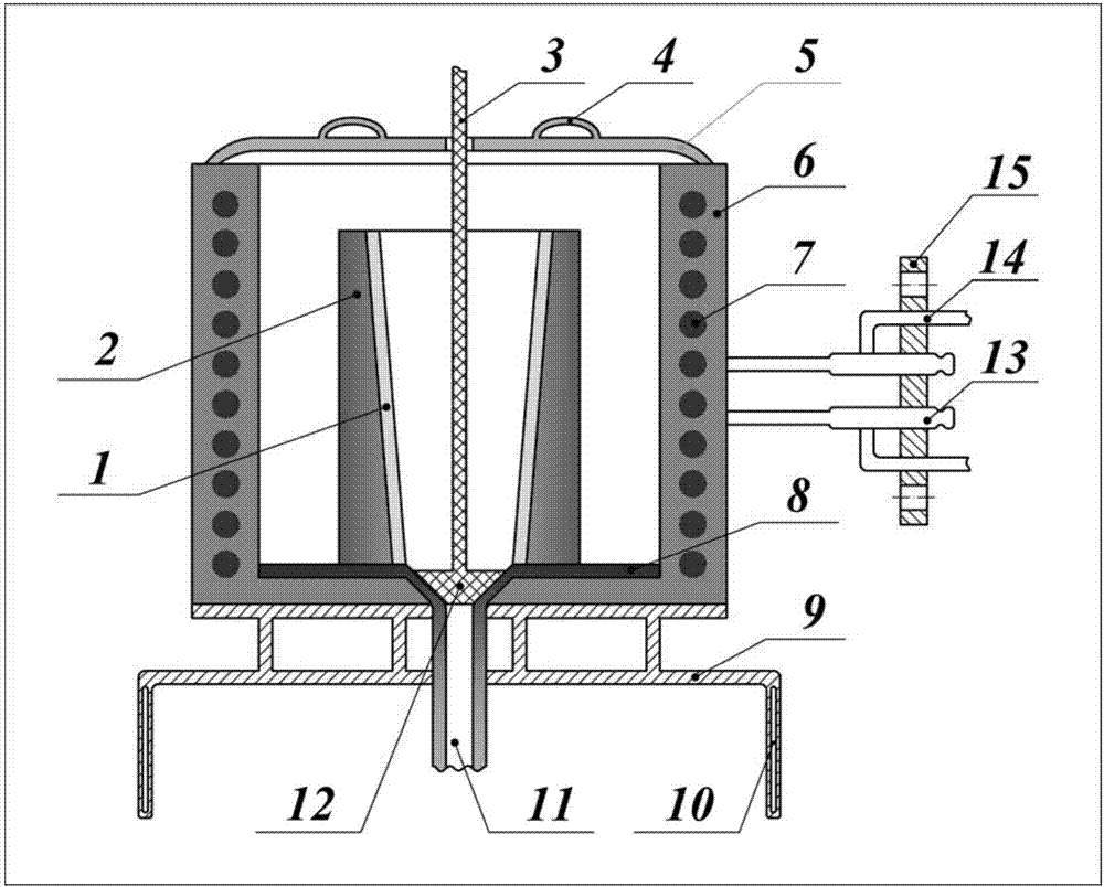
[0027] like figure 1 As shown, the present invention is a multipurpose electromagnetic induction smelting device, said device is based on the principle of electromagnetic induction heating, comprising a zirconia crucible 1, a graphite crucible 2, a ceramic lifting rod 3, a top cover handle 4, a top cover 5, a magnesium oxide crucible Sand knotted body 6 , electromagnetic induction coil 7 , conical funnel 8 , support structure 9 , ceramic draft tube 11 , ceramic plug 12 , and power terminal 13 and cooling pipeline 14 embedded in flange 15 .

[0028] The zirconia crucible 1 is an inverted cone, which is a place for heating and melting materials. It is located in the center of the entire melting device, and its size is determined according to the maximum melting capacity; The geometric structure of the zirconia crucible 1 is turned and milled, and finally...


PUM


Abstract

A multi-purpose electromagnetic induction melting device and a method are disclosed. The multi-purpose electromagnetic induction melting device comprises a zirconia crucible, a graphite crucible, an electromagnetic induction coil, a upper-portion top cover, a conical funnel, a ceramic flow guide pipe, a ceramic plug, a supporting mechanism, power-line terminals and cooling pipelines; the zirconia crucible is arranged in the graphite crucible and serves as a place for material melting, and the graphite crucible has magnetic conductivity and emits heat under the effect of eddy currents; the electromagnetic induction coil is placed at the outer portion of a double-layer crucible and subjected to sintering protection by adopting magnesite, and can be used in a corrosion environment; the power-line terminals and the cooling pipelines of the electromagnetic induction coil are all welded to a flange plate, and seamless connection with a sealed container can be achieved; the zirconia crucible is connected with the ceramic flow guide pipe through the conical funnel at the bottom and cooperates with the ceramic plug to control opening and closing of a crucible bottom hole; and the whole device is fixedly connected with a base or the inner wall of a container through the supporting structure at the bottom of the device. The multi-purpose electromagnetic induction melting device can be used in severe environments such as the corrosion environment, and electromagnetic induction melting and casting of materials are achieved.

Description

technical field [0001] The invention relates to the technical field of smelting, in particular to a multipurpose electromagnetic induction smelting device and method. Background technique [0002] In industries such as smelting and metallurgy, the principle of medium frequency or high frequency electromagnetic induction heating is usually used to melt and pour materials, and an alternating magnetic field is generated by applying an alternating current to the induction coil. The atoms in the magnetic material move randomly under the action of eddy currents to generate heat, that is, to convert electrical energy into heat energy. However, for materials with poor magnetic permeability, the requirements for heat insulation and heating environment are extremely high when resistance heating is used, the cost is high, and the heating efficiency is extremely low at high temperatures; when electromagnetic induction is used to heat it, due to its own There is almost no eddy current, ...

Claims


Application Information

Patent Timeline
Patent Type & Authority Applications(China)
IPC IPC(8): F27B14/06F27B14/10F27B14/14F27B14/18F27B14/08
CPCF27B14/061F27B14/08F27B14/0806F27B14/10F27B14/14F27B2014/0818F27B2014/0837F27M2003/13
Inventor 苏光辉张亚培田文喜秋穗正胡亮
Owner XI AN JIAOTONG UNIV
Why Eureka
Try Eureka