Pushing-rod single-movable-tooth efficient lubricant transmission four-cylinder internal combustion engine

A technology for internal combustion engines and movable teeth, which is applied in the field of four-cylinder internal combustion engines with high-efficiency lubrication and transmission of single movable teeth of push rods. Achieve the effects of eliminating eccentric wear, preventing crankshaft burning or locking, and eliminating energy consumption

Inactive Publication Date: 2017-12-01
邱秀芳
View PDF6 Cites 4 Cited by
  • Summary
  • Abstract
  • Description
  • Claims
  • Application Information

AI Technical Summary

Problems solved by technology

Therefore four-stroke internal-combustion engine crankshaft linkage has the following disadvantages: 1. Since the internal-combustion engine utilizes the connecting rod crankshaft to convert the reciprocating motion of the piston into circular motion, when the compression stroke of the cylinder ends, it is at the top dead center of the expansion power stroke. Gas combustion makes the maximum pressure in the cylinder and produces the strongest thrust, but at this time in the crank-link mechanism, the crankshaft and the connecting rod are in a straight line, that is, the force arm is zero, that is, there is no power output at this time, that is, no work is done to the outside; and because The circular motion of the crankshaft will inevitably cause the angle change of the connecting rod connected to the crankshaft, and the power is scattered and only part of the power can be transmitted. Therefore, the crankshaft connecting rod mechanism makes the heat energy utilization rate of the internal combustion engine very low; 2. The direction of the connecting rod and the piston movement exists The angle between the piston and the inner wall of the cylinder block will produce a certain friction force. The larger the angle between the connecting rod and the piston movement direction, the greater the friction force. When the piston runs in the cylinder, the friction force generated by the cylinder wall is uneven. Therefore, after the piston moves at high speed for a long time in the cylinder, it is easy to cause eccentric wear, which will damage the inner wall of the cylinder or the piston and cause air leakage, so that the heat utilization rate of the internal combustion engine will decrease. This is a problem that has not been solved since the use of the crankshaft connecting rod internal combustion engine.
However, at present, the fundamental task of the lubricating oil delivery device for internal combustion engines is to continuously supply lubricating oil with clean, certain pressure and suitable temperature to the friction surfaces of moving parts so that the internal combustion engine can work normally. Therefore, the lubricating oil delivery device for internal combustion engines must have An oil pump with sufficient oil pressure, but there are some problems when using an oil pump in a crankshaft connecting rod internal combustion engine: 1. As a component, the oil pump needs to occupy a certain space in the internal combustion engine, which leads to an increase in the volume of the internal combustion engine. Independent running parts must consume a certain amount of energy; 2. Due to the complex structure of the crankshaft, the lubricating oil needs to be under strong pressure to ensure better lubrication protection for the crankshaft. However, the oil pump generally has low pressure and It is easy to cause the crankshaft to burn or lock the phenomenon, so that the internal combustion engine wears quickly and the life is short; 3. The cost of the oil pump is relatively high. As a necessary part of the internal combustion engine, the manufacturing cost of the internal combustion engine increases

Method used


Image

  • Pushing-rod single-movable-tooth efficient lubricant transmission four-cylinder internal combustion engine
  • Pushing-rod single-movable-tooth efficient lubricant transmission four-cylinder internal combustion engine
  • Pushing-rod single-movable-tooth efficient lubricant transmission four-cylinder internal combustion engine

Examples


Embodiment Construction

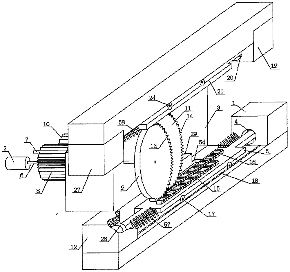
[0022] Such as figure 1 and Image 6 As shown, the four-cylinder internal combustion engine of the push rod single movable tooth high-efficiency lubrication transmission of the present embodiment includes a cylinder, a transmission shaft 2, a lubricating oil tank, a lubricating oil delivery device, and an internal combustion engine body 3. A piston is arranged in the cylinder, and the internal combustion engine body 3 is fixed by a bearing. There is a driving shaft 6 and a driven shaft 7, and the outer end of the driving shaft 6 fixed on the internal combustion engine body 3 is a power transmission shaft 2. The active rotating shaft 6 is provided with an active toothed disc 8 and an active movable toothed disc 9, and the active rotating shaft 6 between the active toothed disc 8 and the active movable toothed disc 9 is provided with a bearing and is fixed with the internal combustion engine body 3. The driven shaft 7 is provided with a driven toothed disc 10 meshing with the a...


PUM


Abstract

The invention discloses a pushing-rod single-movable-tooth efficient lubricant transmission four-cylinder internal combustion engine, and relates to the field of internal combustion engine transmission. The problems that a current crankshaft connecting rod internal combustion engine is large in volume, prone to eccentrically being worn, high in energy consumption, low in power, high in manufacturing precision and the like are solved. A engine body of the pushing-rod single-movable-tooth efficient lubricant transmission four-cylinder internal combustion engine is fixedly provided with a driving rotating shaft and a driven rotating shaft through a bearing. A driving movable tooth and a driven movable tooth are half of a driving movable tooth disc and a driven movable tooth disc. A first air cylinder and a third air cylinder are corresponding arranged on the side, where the driving movable tooth disc is located on, of the driving movable tooth disc, a second air cylinder and a fourth air cylinder are corresponding arranged on the side, where the driven movable tooth disc is located on, of the driven movable tooth disc. A first pushing rod and a second pushing rod are correspondingly connected with a first lubricating oil conveying device and a second lubricating oil conveying device. The pushing-rod single-movable-tooth efficient lubricant transmission four-cylinder internal combustion engine is simple in structure and small in volume, eccentric wear prevention is achieved, the energy consumption is low, and the effective power is greatly improved.

Description

technical field [0001] The invention relates to the technical field of internal-combustion engine transmission, in particular to a four-cylinder internal-combustion engine with a push rod single movable tooth and high-efficiency lubrication transmission. Background technique [0002] At present, the traditional piston internal combustion engine mostly uses the cylinder as the power unit. The piston is connected with the crankshaft through the piston pin and the connecting rod. The crank connecting rod is used as the transmission device. The connecting rod is connected with a flywheel. Rotation; In order to inhale fresh gas and discharge exhaust gas, there are intake valves and exhaust valves. The farthest distance between the piston top and the center of the crankshaft is called the top dead center, and the place where the piston top is closest to the center of the crankshaft is called the bottom dead center. Relying on the expansion force generated by the combustion of mixe...

Claims


Application Information

Patent Timeline
Patent Type & Authority Applications(China)
IPC IPC(8): F02B75/32F02B75/18F01M1/04F01M1/08F01M1/16F16H19/04
CPCF02B75/32F01M1/04F01M1/08F01M1/16F02B75/18F02B2075/1816F16H19/043
Inventor 邱秀芳
Owner 邱秀芳
Why Eureka
Try Eureka