Helical fiber grating manufacturing device and manufacturing method thereof

A fiber grating and manufacturing device technology, applied in the directions of cladding fiber, optical waveguide light guide, light guide, etc., can solve the problems of complicated manufacturing equipment, complicated manufacturing process and low efficiency of helical fiber grating, and achieve strong repeatability and manufacturing efficiency. High and low cost effect

Active Publication Date: 2017-12-12
XIAMEN UNIV
View PDF4 Cites 1 Cited by
  • Summary
  • Abstract
  • Description
  • Claims
  • Application Information

AI Technical Summary

Problems solved by technology

[0005] The purpose of the present invention is to solve the problems of complex manufacturing equipment, high cost, complicated manufacturing process, and low efficiency of spiral fiber gratings, and provide a simple, low-cost, and efficient production of a wide range of adjustable fiber diameter and helical period. Spiral fiber grating manufacturing device and manufacturing method thereof

Method used


Image

  • Helical fiber grating manufacturing device and manufacturing method thereof
  • Helical fiber grating manufacturing device and manufacturing method thereof

Examples


Embodiment Construction

[0017] The present invention will be further described below in conjunction with the accompanying drawings and specific embodiments.

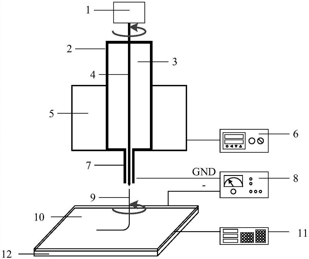
[0018] combine figure 1 , the flat end of the metal rod 4 with a needle point is connected with the DC motor 1 through a coupling, and the needle tip of the metal rod 4 slightly protrudes from the metal microchannel 7; the center of the metal cap on the upper end of the metal storage tube 2 is punched so that the metal rod can pass through The other end is connected to the metal microchannel through a standard interface; the heater 5 is in close contact with the metal storage pipe 2, and the temperature of the molten polymer raw material 3 in the storage pipe 2 is adjusted by the temperature controller 6; the metal microchannel 7 is connected to the ground terminal of the high-voltage DC power supply 8; the conductive substrate 10 is connected to the negative voltage terminal of the high-voltage DC power supply 8, and is insulated and placed on...


PUM


Abstract

The invention discloses a helical fiber grating manufacturing device and a manufacturing method thereof and relates to helical fiber gratings. The device comprises a direct current motor, a storage pipe, a metal rod, a heater, a temperature controller, a micro-channel, a power supply, a conductive base, a translation stage controller and an X-Y-axis precision translation stage. The manufacturing method comprises the following steps: adding electrostatic spinning raw materials into the storage pipe, regulating the temperature controller to heat so as to remove the moisture in the raw material, and regulating the temperature to the melting point of the raw materials; inserting the metal rod into a melt polymer, extending out of a discharge hole below the micro-channel, and regulating the rotating speed of the direct current motor until the needle tip is coated by the melt polymer, so that the molten liquid stably flows out; switching on the power switch, regulating the voltage of the conductive base to a preset negative pressure, starting the electrostatic spinning process, collecting electrospun fibers on the conductive base, reducing the temperature for curing in the deposition process, and forming a helical structure; enabling the X-Y-axis precision translation stage to drive the conductive base to move by virtue of the translation stage controller, thereby obtaining the helical fiber grating with the controllable diameter and screw pitch.

Description

technical field [0001] The invention relates to a spiral optical fiber grating, in particular to a spiral optical fiber grating manufacturing device and a manufacturing method thereof. Background technique [0002] The spiral fiber grating was first proposed by Kopp et al. in 2003. It is made of a quartz fiber with non-circular symmetry in the molten state and twisted at high speed. It has periodic refractive index modulation along the angular direction and the longitudinal propagation direction. It is a A new type of optical waveguide structure. It not only has the wavelength selection characteristics of traditional fiber gratings, but also has the polarization sensitivity characteristics that traditional fiber gratings do not have. The circularly polarized polarizer based on it has important applications in coherent optical communication, current sensing, and fiber optic gyro (Z .Lin, A.Wang, L.Xu, and et al., Generation of optical vortices using ahelical fiber Bragg grat...

Claims


Application Information

Patent Timeline
Patent Type & Authority Applications(China)
IPC IPC(8): G02B6/02
CPCG02B6/02123G02B6/02176
Inventor 陈沁楠孙道恒吴德志梅学翠陈小军方可
Owner XIAMEN UNIV
Why Eureka
Try Eureka