Movable straw compact forming equipment in field

A molding equipment and mobile technology, applied in the direction of packaging/bundling items, application, presses using rotating pressure members, etc., can solve the problems that are not conducive to long-term stability of straw molding and moisture retention, unfavorable transportation and storage, green preservation and moisture storage , Unable to match the field operation system and other problems, to avoid excessive extrusion resistance, prolong the continuous operation time, reduce the number and frequency of shutdown maintenance

Active Publication Date: 2017-12-15
ANYANG INST OF TECH
View PDF10 Cites 9 Cited by
  • Summary
  • Abstract
  • Description
  • Claims
  • Application Information

AI Technical Summary

Problems solved by technology

This technical solution does not have a wrapping and binding device, which is not conducive to the long-term stability of straw forming and moisture retention, and is not conducive to silage; the patent CN204616471U authorizes the "screw-propelled bundling and wrapping machine", which uses three-way screw propulsion to compress the material. Fiber bag packing material
Since the material block is pushed into the fiber bag, the fiber bag has no wrapping force on the material block, it is relatively loose, and the stability of the formed material block is insufficient; in summary, these devices have the following problems during use: First, these The equipment has different degrees of deficiencies in the compactness of the material block, which is not conducive to transportation and storage, green preservation and water storage; secondly, the equipment with compression function in these equipments generally uses oil cylinders for compression molding of straw, and Oil cylinders are used in at least two dimensions, and some even use oil cylinder compression in three dimensions. Although this method can obtain relatively dense compressed blocks, because the oil cylinder has a return stroke during compression, continuous feeding cannot be achieved during operation. , the operating phase rate is relatively low; the third is that these equipments are formed by pressure. A throat constriction part, the size of the section of the throat constriction part is slightly smaller than that of the molding chamber, which is equivalent to the size of the shape-preserving chamber, increasing the resistance of the material block to promote the dense compression of the material block, and when the material block passes through the throat constriction part, it is further compressed and then enters the shape-preserving chamber Channel, the shape-preserving channel is also called the shape-preserving room. The throat constriction part of the current straw forming device is surrounded by steel plates and is fixed. Although it can play the role of throat constriction during the forming process, it cannot The medium is severely worn and needs to be replaced frequently. Furthermore, in the straw molding process, the characteristics of the material are not stable, which leads to different friction forces when the material formed during compression molding is retracted. The current form of throat shrinkage is It is impossible to take into account the characteristics of various materials in the design, resulting in poor adaptability and high damage rate. The straw molding operation is a seasonal and time-sensitive operation. If some parts are often damaged during use, it will become the whole The short board of the equipment leads to the short continuous operation time, which seriously affects its operation efficiency and annual income; the fourth is that the forming process and shaping process are adopted in the forming of straw, the forming process adopts compression molding, and the shaping process first adopts rope body The material block is wound, and then the material block after winding the rope body is coated, and the rope body is used to wind the material block in the forming equipment, which requires a special winding mechanism, and also requires the use of a knotter, a knotter At present, it is basically all imported, and the price is expensive. This type of shaping equipment has a complex structure and high cost. In addition, in this shaping process, the joint between the plastic film and the rope body other than the material block is tight during coating, which is easy to cause the rope body become loose, which causes the loosening of the material block, resulting in the loss of moisture
In addition, most of the current field walking equipment can only realize some functions in picking, forming, bundling, and coating, and cannot be matched into a complete field operation system

Method used


Image

  • Movable straw compact forming equipment in field
  • Movable straw compact forming equipment in field
  • Movable straw compact forming equipment in field

Examples


Embodiment Construction

[0021] In order to more fully explain the implementation of the present invention, implementation examples of the present invention are provided. These implementation examples are only illustrations of the present invention, and do not limit the scope of the present invention.

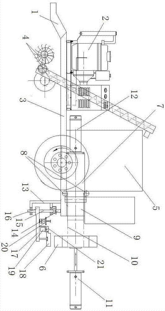
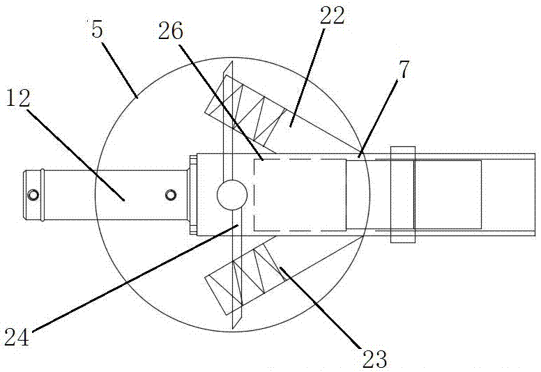
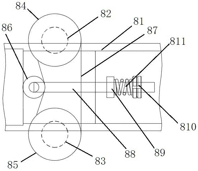
[0022] A further detailed explanation of the present invention will be given in conjunction with the accompanying drawings. In the accompanying drawings, each mark is: 1: traction mechanism; 2: power device; 3: traction platform; 4: straw picking and conveying mechanism; 5: buffer bin; Wrapping mechanism; 61: guide roller; 62: rope frame and rope tensioner; 63: film frame and film tensioner; 64: C-shaped swivel; 7: forming room; 8: roller throat mechanism; 81: shape retention Channel housing; 82: upper squeeze roller; 83: lower squeeze roller; 84: upper right guide wheel; 85: lower right guide wheel; 86: right adjustment wheel; 87: right tightening chain / belt; 88: right adjustment screw ;89: Right gui...


PUM

PropertyMeasurementUnit
angleaaaaaaaaaa

Abstract

The invention discloses movable straw compact forming equipment in the field. The equipment comprises a field walking traction mechanism and a straw pickup and conveying mechanism. The traction mechanism is provided with a traction platform, a power device is arranged on the traction mechanism, the traction platform is provided with a buffer bin, and an outlet of the straw pickup and conveying mechanism is located on the buffer bin. The movable straw compact forming equipment in the field further comprises a compact forming mechanism, a roller type throat shrinkage mechanism and a shaping mechanism. According to the movable straw compact forming equipment in the field, a main pressure oil cylinder is large in acting force and high in compactness degree; the throat shrinkage portion is long in service life, a composite winding mechanism is adopted for winding a rope body and a plastic film, an expensive and complex knot tying device is omitted, and the equipment cost is reduced. In the field walking process after the equipment initially completes straw cutting, the pickup, forming and film coating can be completed for straw, and the efficiency is high.

Description

technical field [0001] The invention relates to straw molding equipment, in particular to field mobile straw molding equipment, and belongs to the technical field of agricultural machinery. Background technique [0002] Most of the straws of traditional crops in China are discarded or burned on the spot by farmers, which not only wastes resources, but also causes air pollution and damages the ecology and natural environment. However, in the process of development and utilization of crop straw, due to its loose structure and scattered distribution, it brings great difficulties to collection, transportation and storage, and its low energy density makes it very inconvenient to use. One of the measures to solve this problem is to use straw molding technology to extrude loose and finely divided amorphous straw into dense, regular-shaped shaped fuel or feed. Although many studies have been carried out in related fields such as biomass extrusion molding technology, in actual opera...

Claims


Application Information

Patent Timeline
Patent Type & Authority Applications(China)
IPC IPC(8): B30B3/00B30B15/00B30B15/06B30B9/30B30B15/30B30B15/32A01D89/00B65B11/02
CPCA01D89/001B65B11/025B30B3/005B30B9/3021B30B15/30B30B15/32Y02E50/30Y02E50/10
Inventor 王美美张勇韩文清王咏梅张瑜马淑叶
Owner ANYANG INST OF TECH
Why Eureka
Try Eureka