Screenless flow-through battery material dryer

A battery material and dryer technology, applied in the direction of drying gas arrangement, drying, drying machine, etc., can solve the problems of house construction, operation and equipment maintenance, unsmooth air flow, and powder blockage of the screen, etc., to achieve Reliable drying effect, convenient manufacturing and installation, and not easy to block

Active Publication Date: 2019-04-19
HEBEI UNIV OF TECH +1
View PDF7 Cites 0 Cited by
  • Summary
  • Abstract
  • Description
  • Claims
  • Application Information

AI Technical Summary

Problems solved by technology

But there are also some defects in the airflow dryer. As the application number is 201310313792.3 Chinese patent discloses a long-tube airflow dryer. Inconvenience
In addition, as the Chinese patent No. 03250884.0 discloses a Venturi drier, its air inlet is below the drier, and generally requires a sieve to hold the powder to be dried, and the aperture of the sieve is smaller than that of the dried powder. diameter, it will easily cause the powder to block the screen, even if the screen is not blocked, the air flow will not be smooth because the screen aperture is too small

Method used


Image

  • Screenless flow-through battery material dryer
  • Screenless flow-through battery material dryer

Examples


Embodiment Construction

[0020] Specific embodiments of the present invention are given below. The specific embodiments are only used to further describe the present invention in detail, and do not limit the protection scope of the claims of the present application.

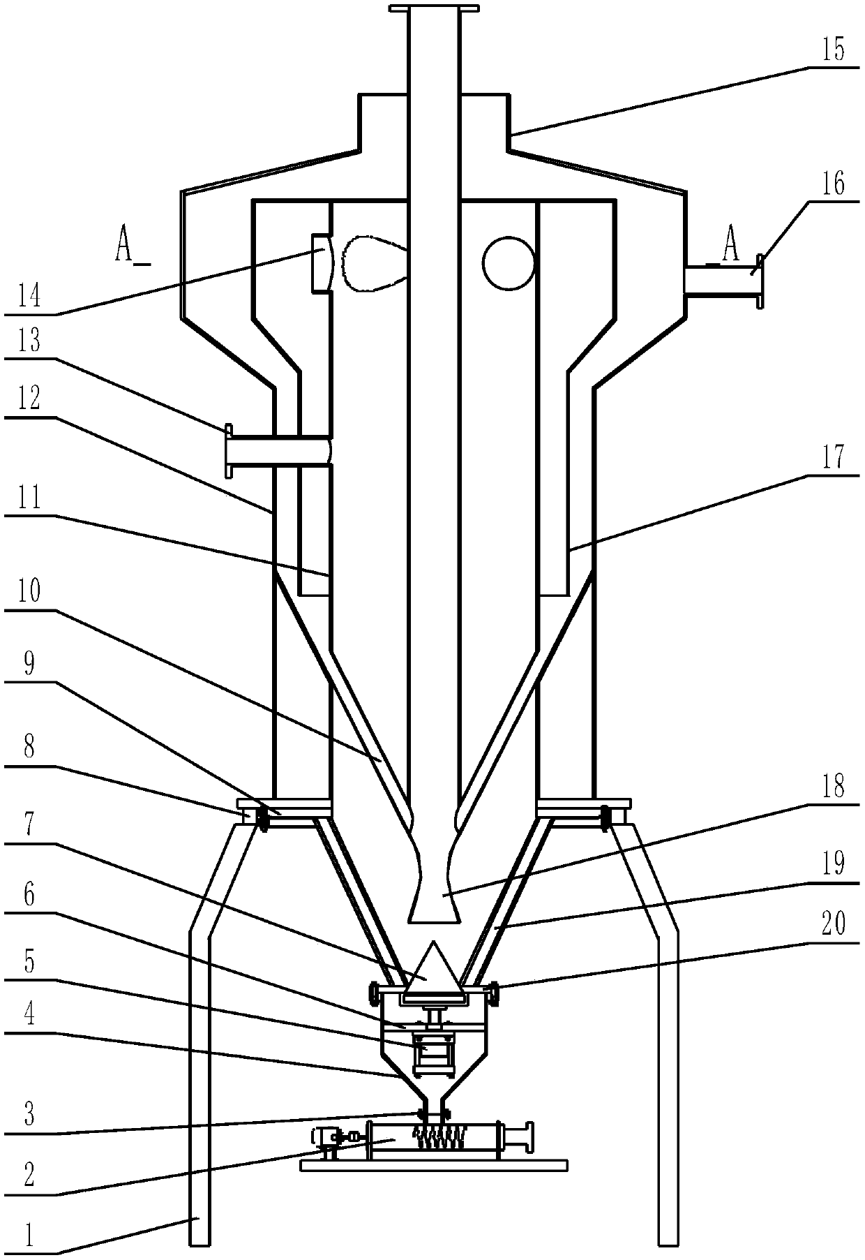
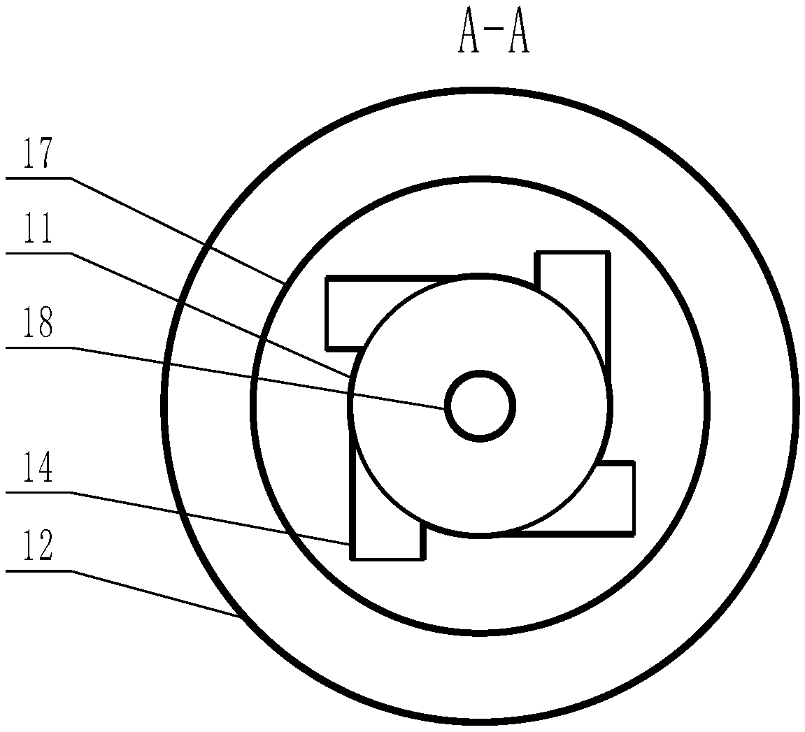
[0021] The present invention has no sieve mesh flow-washing type battery material drier (abbreviation drier, see figure 1 ) includes bracket 1, screw feeder 2, first flange 3, discharge pipe 4, cylinder 5, blanking plate 6, sealing piston 7, weighing device 8, second flange 9, venturi branch 10 , air flow tank (not marked in the figure), return air tank 12, feed pipe 13, cyclone outlet pipe 14, return air pipe 15, vacuum tube 16, return tank 17, Venturi tube 18 and the third flange 20;

[0022] Described airflow jar comprises airflow jar upper section 11 and airflow jar lower section 19, and airflow jar upper section 11 and airflow jar lower section 19 are communicated, and the upper outside of airflow jar upper section 11 is set return...


PUM


Abstract

The invention relates to a flow-washing-type battery material dryer free of a screen cloth. The flow-washing-type battery material dryer free of the screen cloth is characterized in that the dryer comprises a support, a spiral material feeder, a first flange plate, a discharging pipe, an air cylinder, a material dropping plate, a sealing piston, a weighing device, a second flange plate, a Venturi branched tube, an airflow tank, a return air tank, a feeding pipe, a cyclone air outlet pipe, an air return pipe, a vacuum pumping pipe, a reflux tank, a Venturi tube and a third flange plate; the airflow tank comprises an upper airflow tank section and a lower airflow tank section, and the upper airflow tank section and the lower airflow tank section communicate with each other; the reflux tank is arranged at the outer side of the upper portion of the upper airflow tank section in a sleeving mode; the upper end of a space between the reflux tank and the upper airflow tank section is closed, and the lower end of the space is opened; and the reflux tank is of a cylinder structure with the cross section circle variable. According to the flow-washing-type battery material dryer, the return air tank, the reflux tank, the airflow tank and the Venturi tube are sequentially nested from outside to inside, so that the heat preservation effect of the dryer is made good; and moreover, heat is transmitted between the multiple layers of the pipes, after all layers of pipe walls are heated by hot air, the heat can be radiated outwards from the pipe walls, and powder drying is accelerated.

Description

technical field [0001] The invention relates to an airflow drier, in particular to a screenless flow washing type battery material drier. Background technique [0002] Airflow drying is a continuous high-efficiency solid fluidized drying method. After the airflow is heated, the powder is blown and floated. During the blowing and floatation process, full contact and heat exchange are carried out to vaporize the moisture in the powder, thereby obtaining dry powder. The purpose of drying is to remove the moisture or solvent in the powder. As far as battery materials are concerned, the purpose is to dry the powder to improve the quality of the battery. [0003] Airflow drying is widely used in industrial production, and has the advantages of high drying strength, short drying time, large processing capacity, simple equipment, and convenient operation. But there are also some defects in the airflow dryer. As the application number is 201310313792.3 Chinese patent discloses a lo...

Claims


Application Information

Patent Timeline
Patent Type & Authority Patents(China)
IPC IPC(8): F26B17/10F26B21/00
CPCF26B17/10F26B21/004
Inventor 关玉明尹雪瑶王俊涛王骁王进刘树根葛浩何川
Owner HEBEI UNIV OF TECH
Why Eureka
Try Eureka