Full-automatic silicon chip inserting machine

A fully automatic technology for inserting silicon wafers, applied in the direction of conveyor objects, electrical components, climate sustainability, etc., can solve problems that cannot fully meet the insertion process, do not meet the requirements of the manufacturer, and cause high pressure on silicon wafers , to achieve reasonable equipment cost, improve the degree of production automation, and fast insertion speed

Pending Publication Date: 2018-01-05
昆山安谷自动化设备有限公司
View PDF1 Cites 5 Cited by
  • Summary
  • Abstract
  • Description
  • Claims
  • Application Information

AI Technical Summary

Problems solved by technology

In the past, most factories used manual insertion, which was labor-intensive and inefficient, and silicon wafers often broke when workers were inserting them.
Later, a silicon chip insertion machine appeared, which has the advantages of simple structure, easy installation, convenient operation, high degree of automation, improved work efficiency, and reduced fragmentation rate, but it still cannot fully meet the requirements of the insertion process. With the rapid development of the solar energy industry, manufacturers are demanding The quality requirements of silicon wafers are getting higher and higher. At present, the silicon wafer inserting machines on the market use vacuum suction cups to grab silicon wafers.
For example, the invention patent application

Method used


Image

  • Full-automatic silicon chip inserting machine
  • Full-automatic silicon chip inserting machine
  • Full-automatic silicon chip inserting machine

Examples


Embodiment Construction

[0027] In order to make the object, technical solution and advantages of the present invention clearer, the present invention will be further described in detail below in combination with specific examples and with reference to the accompanying drawings. It should be understood that these descriptions are exemplary only, and are not intended to limit the scope of the present invention. Also, in the following description, descriptions of well-known structures and techniques are omitted to avoid unnecessarily obscuring the concept of the present invention.

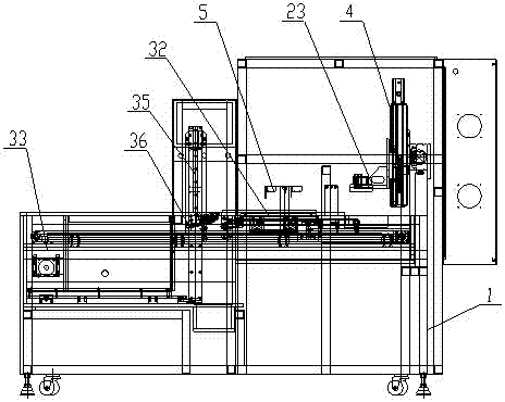
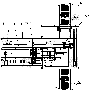
[0028] Such as figure 1 As shown, a fully automatic silicon chip inserting machine includes a frame 1, a flower basket conveying device 2 and a slice inserting device 3 arranged on the frame 1; the flower basket conveying device 2 includes an empty flower basket conveying line 21 1. The loaded flower basket conveying line 22 and the mechanical arm 23 for transferring and lifting the flower basket, the empty flower basket co...


PUM


Abstract

The invention discloses a full-automatic silicon chip inserting machine, which comprises a rack, a basket conveying device and a chip separating and inserting device, and is characterized in that thebasket conveying device comprises an empty basket conveying line, a loaded basket conveying line and a mechanical arm, and the empty basket conveying line and the loaded basket conveying line are oppositely arranged at two sides of the rack, and the mechanical arm is arranged at the upper part of the rack and capable of moving freely; the chip separating and inserting device comprises a chip separating water tank and a silicon chip conveyor belt, a backflow tank is arranged beside the chip separating water tank, the chip separating water tank and the backflow tank are internally provided witha magnetic pump circulation system, the chip separating water tank is internally provided with a main tank inlet, the bottom of the main tank inlet is provided with a bottom assembly line for conveying a basket, the tail end of the bottom assembly line is provided with a lifting jig, the upper part of the lifting jig is provided with a water spraying device, and the other end of the silicon chip conveyor belt is provided with a chip inserting fixture controlled by the mechanical arm to move up and down. The full-automatic silicon chip inserting machine has the beneficial effects that all operations are automatically completed through the equipment, the automation degree is high, the production efficiency is high, and the silicon chips are not easy to be broken or have other faults.

Description

technical field [0001] The invention relates to the technical field of solar battery chip manufacturing equipment, in particular to a fully automatic silicon chip inserting machine with high automation, high production efficiency and unbreakable silicon chips. Background technique [0002] Since the beginning of the 21st century, global energy consumption has risen sharply, and traditional fossil energy has been increasingly exhausted. Energy issues and environmental issues have gradually become two major issues of global concern. Under the pressure of sustainable development, major countries have listed the solar photovoltaic industry as the focus of the development and utilization of renewable energy. With my country becoming the second largest economy in the world, in October 2013, China's oil imports in October reached 6.3 million barrels per day, surpassing the 6.24 million barrels per day of the United States, replacing the United States as the world's largest net oil ...

Claims


Application Information

Patent Timeline
IPC IPC(8): H01L31/18H01L21/677H01L21/66H01L21/67
CPCY02P70/50
Inventor 李毛学
Owner 昆山安谷自动化设备有限公司
Why Eureka
Try Eureka