Concentrated combustion type in-situ thermal desorption repairing device for contaminated site

A technology of concentrated combustion and thermal desorption, which is applied in the restoration of polluted soil, grease/oily substance/suspton removal device, flotation water/sewage treatment, etc. issues of complex nature

Pending Publication Date: 2018-02-13
SHANGHAI GREENMENT ENVIRONMENTAL TECH CO L
View PDF0 Cites 12 Cited by
  • Summary
  • Abstract
  • Description
  • Claims
  • Application Information

AI Technical Summary

Problems solved by technology

[0004] At present, the engineering application of in-situ thermal desorption remediation technology in the remediation of domestic contaminated sites is still relatively limited. The geological conditions of the site and the upper limit of the target temperature limit, the energy cost required for in-situ heating is high, the groundwater flow of the site is not eas

Method used


Image

  • Concentrated combustion type in-situ thermal desorption repairing device for contaminated site
  • Concentrated combustion type in-situ thermal desorption repairing device for contaminated site
  • Concentrated combustion type in-situ thermal desorption repairing device for contaminated site

Examples


Embodiment 1

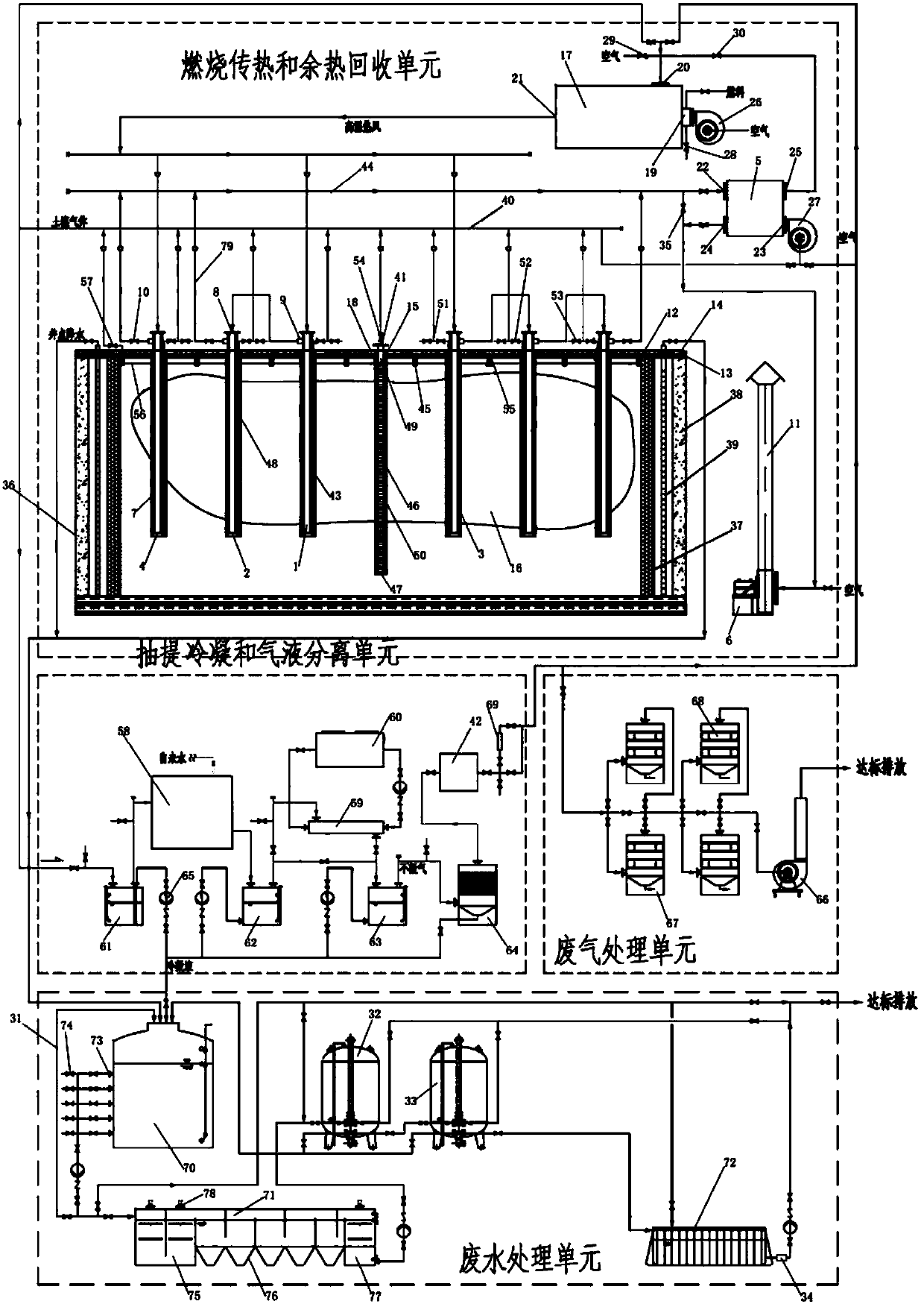
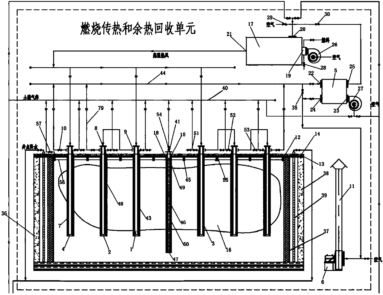
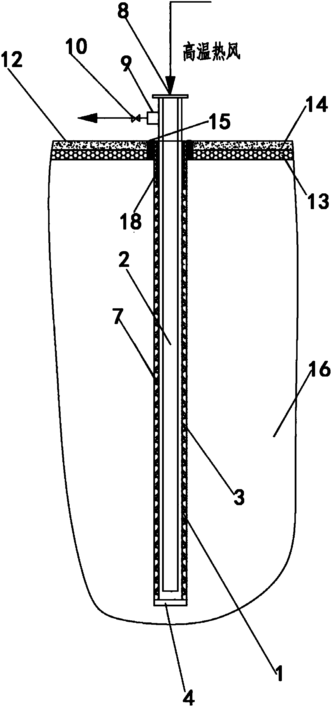
[0044] A centralized combustion in-situ thermal desorption repair device for polluted sites, including combustion heat transfer and waste heat recovery unit, extraction condensation and gas-liquid separation unit, groundwater flow control unit, soil gas control unit, waste gas treatment unit, waste water Processing units and pipelines. The combustion heat transfer and waste heat recovery unit includes a hot blast stove 17, an air-gas heat exchanger 5, a blower, an induced draft fan 6, an exhaust pipe 11, and a group of heating wells. The extraction condensing and gas-liquid separation unit includes extraction well group, heat exchange condensing equipment, gas-liquid separation equipment, demist tower 64 and vacuum pump 42; extraction well group includes several extraction well pipes 41, and extraction well pipe 41 includes vertical Some vertical well type extraction wells 43 installed in the polluted site, and some horizontal well type extraction wells 45 horizontally install...

Embodiment 2

[0064] A centralized combustion in-situ thermal desorption repair device for polluted sites, including combustion heat transfer and waste heat recovery unit, extraction condensation and gas-liquid separation unit, groundwater flow control unit, soil gas control unit, waste gas treatment unit, waste water Processing units and pipelines. The combustion heat transfer and waste heat recovery unit includes a hot blast stove 17, an air-gas heat exchanger 5, a blower, an induced draft fan 6, an exhaust pipe 11, and a group of heating wells. The extraction condensing and gas-liquid separation unit includes extraction well group, heat exchange condensing equipment, gas-liquid separation equipment, demist tower 64 and vacuum pump 42; extraction well group includes several extraction well pipes 41, and extraction well pipe 41 includes vertical Some vertical well type extraction wells 43 installed in the polluted site, and some horizontal well type extraction wells 45 horizontally install...


PUM

PropertyMeasurementUnit
Thicknessaaaaaaaaaa

Abstract

The invention discloses a centralized combustion type in-situ thermal desorption repair device for polluted sites, which comprises combustion heat transfer and waste heat recovery unit, extraction condensation and gas-liquid separation unit, underground water flow control unit, soil gas control unit, waste gas Treatment unit, waste water treatment unit. Combustion heat transfer and waste heat recovery unit includes hot blast stove, air-to-air heat exchanger, blower, induced draft fan, exhaust pipe, and heating well group. The extraction condensing and gas-liquid separation unit includes extraction wells, heat exchange condensing equipment, gas-liquid separation equipment, demister tower, and vacuum pump. The groundwater flow control unit stops the water curtain. The soil gas control unit is a concrete layer. The exhaust gas treatment unit contains adsorption equipment and fans. The wastewater treatment unit includes a regulating tank, a combination tank, sand filter equipment, carbon filter equipment, and a water outlet tank. The centralized combustion type in-situ thermal desorption repairing device for polluted sites provided by the invention can overcome the shortcomings of the prior art and achieve better repairing effects.

Description

technical field [0001] The invention relates to a contaminated site repair device, in particular to a centralized combustion type in-situ thermal desorption repair device for polluted sites. Background technique [0002] Thermal Desorption technology can be widely used in in-situ or ex-situ remediation of volatile organic compounds, semi-volatile organic compounds, petroleum hydrocarbons or mercury-contaminated sites. This technology heats the polluted soil and / or groundwater to close to or even exceed the boiling point of the target pollutant by means of direct or indirect heating, and selectively promotes the desorption, gasification, volatilization, Decompose or increase its mobility, so that the target pollutants can be separated from the soil medium and removed, so as to achieve the purpose of remediation of contaminated sites. [0003] The in-situ thermal desorption remediation technology can be implemented in situ on the polluted site without excavating the polluted ...

Claims


Application Information

Patent Timeline
IPC IPC(8): B09C1/06C02F9/04B01D53/04
CPCB01D53/04C02F9/00B09C1/06B09C1/065C02F1/72C02F1/52C02F1/001C02F1/24C02F1/40C02F2301/08B01D2253/102
Inventor 张峰凃辉王琛马烈王健华顾心爱封卫青
Owner SHANGHAI GREENMENT ENVIRONMENTAL TECH CO L
Why Eureka
Try Eureka