
Visualized correction system of variational inclination angle binocular cone and correction method thereof

A correction system and binocular technology, applied in microscopes, optics, instruments, etc., can solve the problems of high professional quality requirements for installation and calibration technicians, inconvenient mass production of products, and low production efficiency, so as to reduce labor intensity, The effect of expanding production scale and improving production efficiency

Pending Publication Date: 2018-02-27
苏州西默医疗科技有限公司
View PDF9 Cites 3 Cited by
  • Summary
  • Abstract
  • Description
  • Claims
  • Application Information

AI Technical Summary

Problems solved by technology

This means that it is necessary to correct the image jump in the process of changing the inclination angle of the lens barrel. The eyes or the head of the technician must follow the change of the inclination angle of the binocular lens barrel with the variable inclination angle. The greater the swing range, obviously, when correcting the binocular tube with variable inclination angle, this operation method is extremely labor-intensive and the production efficiency is extremely low
In addition, this method of operation has higher requirements on the professionalism of the installation technicians, which is not convenient for mass production of related products

Method used


Image

  • Visualized correction system of variational inclination angle binocular cone and correction method thereof
  • Visualized correction system of variational inclination angle binocular cone and correction method thereof

Examples


Embodiment 1

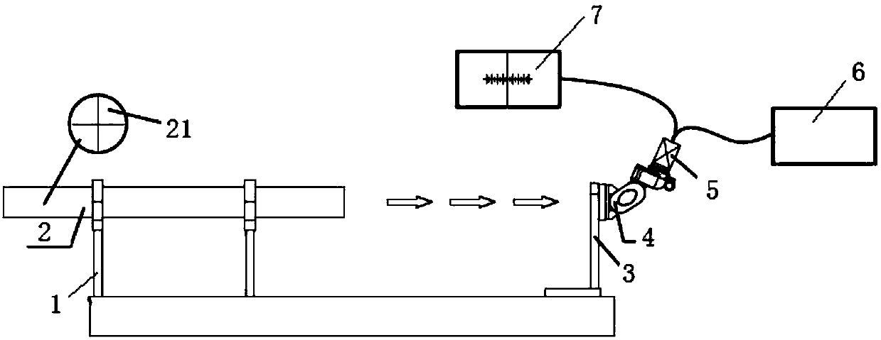
[0017] See figure 1 This specific embodiment discloses a visual correction system and a correction method for a variable tilt binocular tube, including a light pipe bracket 1, a collimator tube 2, a lens tube bracket 3, a binocular tube 4, an industrial camera 5. Camera power supply 6 and display 7. Among them, the camera power supply 6 supplies power to the industrial camera 5 through a power cord to drive its work. The parallel light pipe 2 is fixed by the light pipe holder 1, and the binocular tube 4 is fixed by the lens barrel holder 3. It is feasible that the light pipe holder 1 and the lens barrel holder 3 are welded to the same base for fixing positions.

[0018] Feasible, the industrial camera 5 is embedded with measurement software, which can display a cross-hatched line with a scale on the display 7 through a data line during operation. In this specific embodiment, based on the usual correction method in the field, a cross-shaped reticle is used. Correspondingly, the c...

Embodiment 2

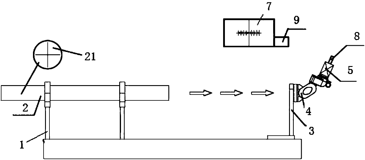
[0022] See figure 2 The difference between the visual correction system and correction method of a variable tilt binocular tube disclosed in this specific embodiment and embodiment 1 is that the camera power supply is not set, the wireless transmission antenna 8 is set on the industrial camera 5, and the display 7 The wireless signal receiver 9 is added, and the cross reference image and the cross-reticle image are displayed on the display 7 through wireless transmission, which can also meet the needs of data transmission and avoid the interference of the power line and the data line to the installation and calibration process .


PUM


Abstract

The invention discloses a visualized correction system of a variational inclination angle binocular cone. The visualized correction system comprises a collimator and the binocular cone, the collimatorexactly faces the binocular cone, an industrial camera is arranged at the other side of the binocular cone, a display is connected to the industrial camera, a cross datum plate is arranged in the collimator, measuring software is embedded in the industrial camera and can display a cross dividing line with scales on the display during work, and the industrial camera is a CMOS camera or a CCD camera. A calibration datum plate is imaged on a target surface of the camera and then the image is transmitted to the display, and by judging the relative position of the image of the calibration datum plate on the display and the cross dividing line, visualized calibration of image jumping of the variational inclination angle binocular cone is achieved, the labor intensity of assembly and calibrationpersonnel is greatly lowered, and the production efficiency is improved; meanwhile, the operation is simple, and the requirement for the personnel is greatly lowered.

Description

Technical field [0001] The invention relates to a microscope accessory, in particular to a visual correction system and a correction method of a variable tilt angle binocular lens barrel. Background technique [0002] The binocular tube is an important part of the optical observation system of the operating microscope. Together with the microscope zoom system, the user of the operating microscope allows the user of the operating microscope to achieve binocular observation of the diseased tissue and generate stereo vision. The binocular tube is generally composed of an objective lens close to the object side (objective lens for short), an optical transfer system that compresses the length or volume of the barrel tube (image transfer system for short), and an eyepiece close to the user's eyes (eyepiece for short). The inclination angle of the eyepiece tube, that is, the angle between the center optical axis of the eyepiece and the main optical axis of the microscope, is one of the ...

Claims


Application Information

Patent Timeline
Patent Type & Authority Applications(China)
IPC IPC(8): G02B21/20G02B21/36G02B27/32
CPCG02B21/20G02B21/368G02B27/32
Inventor 朱剑锋翁海俊黎雁龙严秋峰
Owner 苏州西默医疗科技有限公司
Learn More