
Vacuum paint drawing and vacuum fast drying paint device and process for inner cavity of cooler for transformer

A technology for radiators and transformers, which is applied to the device for coating liquid on the surface, pretreatment of the surface, coating, etc. It can solve the problems of exhaust gas emission pollution, no guarantee of inner cavity quality, and time-consuming, so as to improve production efficiency and protect the environment. Improve the effect and protect the health of workers

Active Publication Date: 2018-03-27
SHENYANG TIANTONG ELECTRICITY
View PDF8 Cites 5 Cited by
  • Summary
  • Abstract
  • Description
  • Claims
  • Application Information

AI Technical Summary

Problems solved by technology

The disadvantage of this method is: due to the large area of ​​the inner cavity of the radiator, there are many channels and narrow gaps, it takes a long time to stand for blowing, and the inner cavity paint needs to be specially dried at about 100°C for several hours, and the inner cavity Although the diluent is vaporized at high temperature, it is still contained in the inner space, and after condensation, it still exists in the inner cavity, posing a hidden danger
Therefore, the painting link is a production bottleneck that consumes energy, emits waste gas and pollutes, and consumes time.
Another defect is that tiny air bubbles may remain in the gaps far away from the inlet and outlet. This method of injecting paint from the lower port with air pressure only needs to repeatedly fill the air bubbles, and it is difficult to eliminate the tiny air bubbles.
The quality of the inner cavity is not guaranteed, which is the bottleneck of current production

Method used


Image

  • Vacuum paint drawing and vacuum fast drying paint device and process for inner cavity of cooler for transformer
  • Vacuum paint drawing and vacuum fast drying paint device and process for inner cavity of cooler for transformer
  • Vacuum paint drawing and vacuum fast drying paint device and process for inner cavity of cooler for transformer

Examples


Embodiment Construction

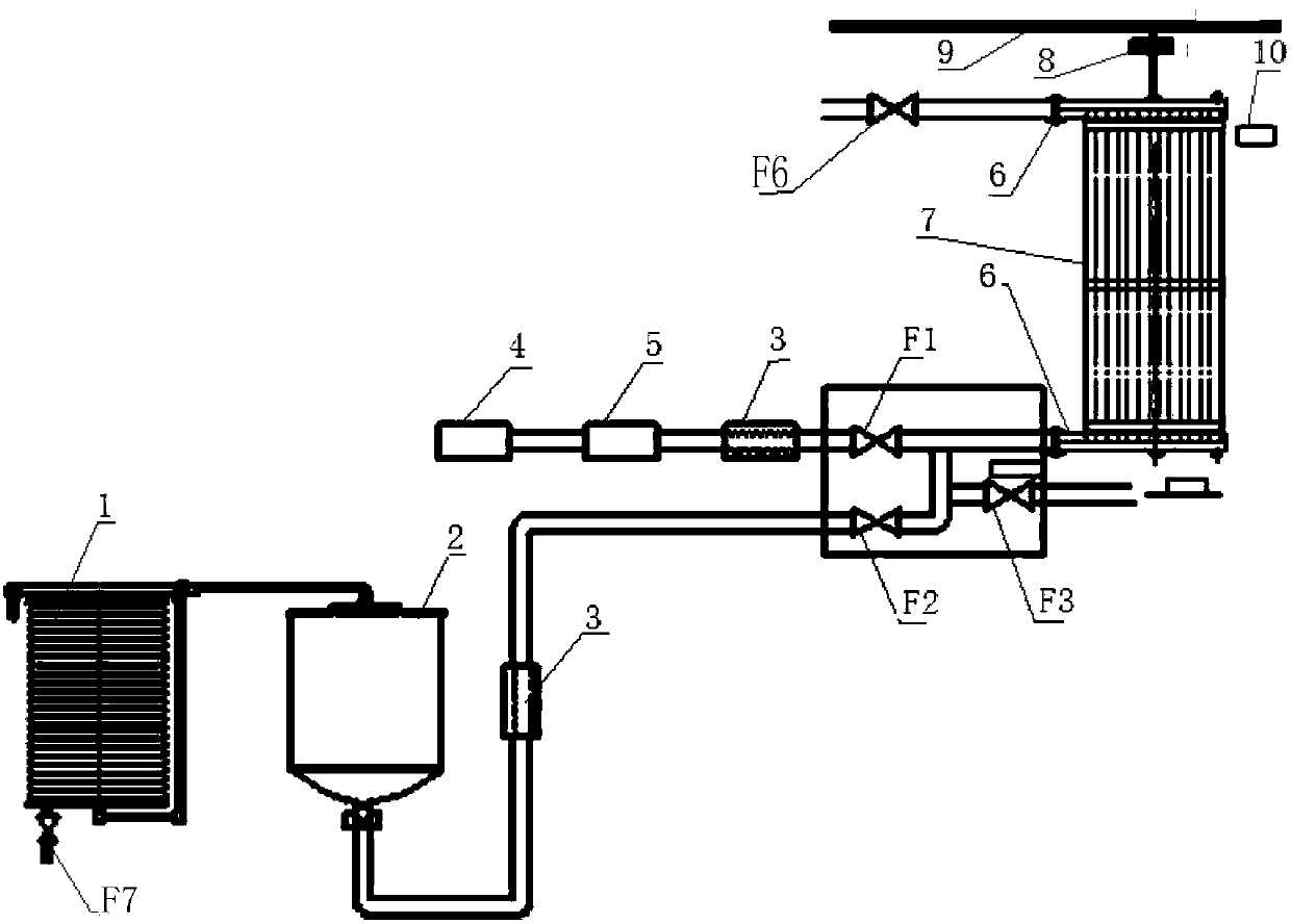
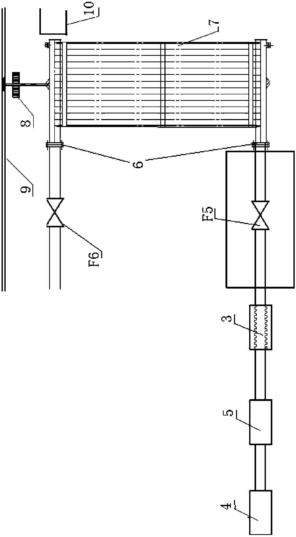
[0014] The arrangement sequence of the equipment of the present invention: including paint storage tank, vacuum system, process control system, exhaust gas recovery and treatment system, track, transmission chain and its motor unit, air duct, workpiece vehicle 9 hanging on the transmission line and control system are arranged on the top of the workshop. The lifting electric hoist 8 is characterized in that the equipment is arranged in the order along the transmission line: the vacuum paint extraction equipment 2, the exhaust fan unit 10, and then the equipment connected to the vacuum quick-drying paint process, all have air ducts connected to the tail gas recovery treatment system; the vacuum method paint extraction equipment , add an exhaust fan unit, and then connect the equipment for the quick-drying paint process; and there is an air duct connected to the exhaust gas recovery treatment system.

[0015] Vacuum pumping equipment: see figure 1 , the vacuum pumping equipment 2...


PUM


Abstract

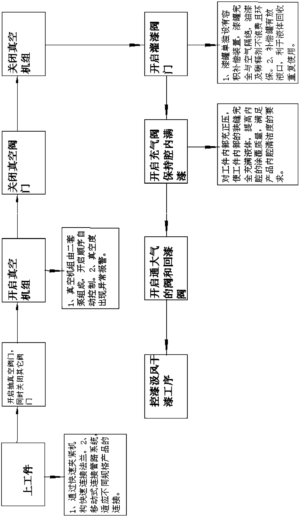
The invention discloses a vacuum paint drawing and vacuum fast drying paint device and process for an inner cavity of a cooler for a transformer. The device is characterized in that the device comprises a vacuum unit, a paint drawing device, an air draft unit, a continuous vacuum unit, a fast drying paint process device are arranged along a conveying line and are communicated with a tail gas recycling treatment system through air ducts; vacuum method paint drawing, air drawing of the air draft unit and the vacuum method fast drying paint are all in online continuous operation; a program controls a conveying chain to run according to CNC in an ID code of a workpiece, the takt interval of the machining time duration is 5-8 min, and the conveying speed is 8-12 m / min; a vacuumizing valve is opened, other valves are closed, a vacuum unit is started, and the sequence of two vacuum pumps is automatically controlled; after the vacuum degree is achieved, paint drawing is performed to automatically control the relevant functionality, and paint drawing is performed on the workpiece; and after paint drawing is full, a compressed air valve is started after a paint drawing valve is closed, pressure is 0.1-0.2 MPa, after pressurizing is completed, a valve communicated with the atmosphere and a paint returning valve are opened, paint in the workpiece flows back to a paint storing tank, and procedure conversion is performed.

Description

technical field [0001] The invention relates to the field of processing, particularly to the manufacture of ultra-high voltage transformers, in particular to a vacuum method and equipment for drawing paint and quick-drying paint for the inner cavity of radiators for manufacturing ultra-high voltage transformers. Background technique [0002] At present, the inner chamber treatment process for the purpose of manufacturing high-voltage and ultra-high-voltage transformer radiators adopts an off-line step-by-step process method. [0003] During the production process of the finned radiator, there will be welding slag and sundries inside. Since the radiator is connected to the transformer, the transformer oil in the transformer communicates with the inner cavity of the radiator, so the debris particles in the inner cavity of the radiator may affect the high temperature. The safety of the voltage transformer has adverse effects, so the cleanliness of the inner cavity of the radiat...

Claims


Application Information

Patent Timeline
Patent Type & Authority Applications(China)
IPC IPC(8): B05C7/04B05C11/10B05C9/12B05D1/00B05D3/04
CPCB05C7/04B05C9/12B05C11/1002B05D1/00B05D3/0406Y02P70/10
Inventor 王天林王冬冬姜洪强宫兴海
Owner SHENYANG TIANTONG ELECTRICITY
Learn More