
Compound cycloidal reducer

A cycloidal reducer, compound technology, applied in the direction of transmission, gear transmission, belt/chain/gear, etc., can solve the problems of difficult complete balance, poor assembly performance of the whole machine, poor axial bending rigidity, etc., and achieve improvement The effect of transmission rigidity and load-carrying capacity, reduction of structural size, and guarantee of machinability

Pending Publication Date: 2018-04-06
CHONGQING UNIV
View PDF0 Cites 0 Cited by
  • Summary
  • Abstract
  • Description
  • Claims
  • Application Information

AI Technical Summary

Problems solved by technology

The disadvantage is that the inertial load acting on the crankshaft of the two-stage cycloidal wheel is difficult to completely balance, which seriously affects the dynamic performance and working reliability of the reducer. Due to the particularity of the structural design, the assembly performance of the whole machine is poor.
Due to the excessive number of transmission stages, the structure design of the reducer is complicated, and the transmission efficiency is difficult to improve
Subsequently, Zhejiang Hengfengtai Reducer Manufacturing Co., Ltd. further proposed an invention patent of "precision cycloid reducer". Higher, but less axial bending stiffness

Method used


Image

  • Compound cycloidal reducer
  • Compound cycloidal reducer
  • Compound cycloidal reducer

Examples


Embodiment Construction

[0017] The technical solution of the present invention will be further described in detail below in conjunction with the accompanying drawings and specific embodiments, and the described specific embodiments are only for explaining the present invention, and are not intended to limit the present invention.

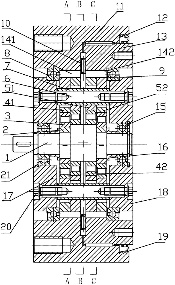
[0018] A compound cycloid reducer proposed by the present invention, such as figure 1 As shown, it includes an input shaft 1 , a fixed pinion housing 12 and an output pinion housing 13 .

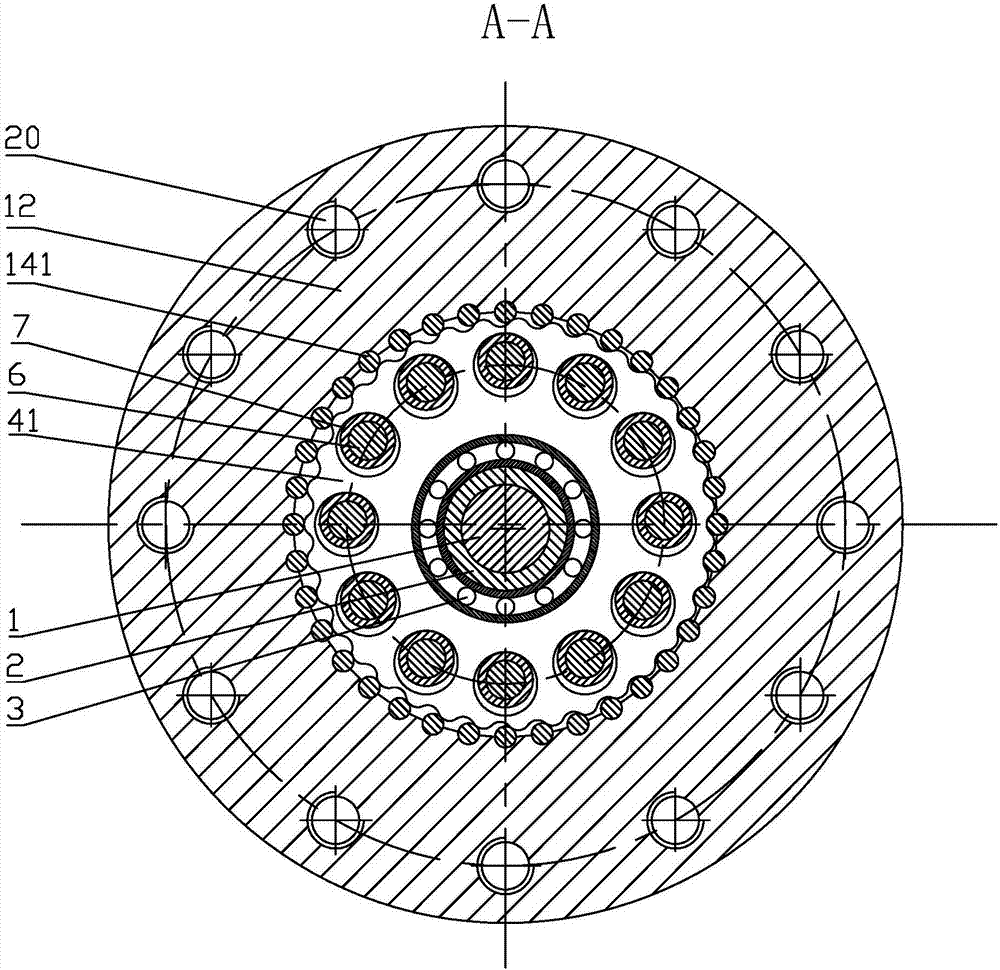
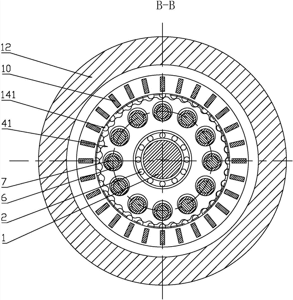
[0019] The input shaft 1 is an eccentric shaft with three eccentric positions, including an eccentric section in the middle and eccentric sections on both sides. Among the eccentric sections on both sides, the left side is the eccentric section on the input side, and the right side is the eccentric section on the output side. The eccentric section is equipped with a first-stage left-set cycloidal wheel 41, and the middle eccentric section is equipped with a first-stage right-set cycloida...


PUM


Abstract

The invention discloses a compound cycloidal reducer. The compound cycloidal reducer comprises an input shaft, a fixed needle tooth shell and an output needle tooth shell; the input shaft is a triple-eccentric-position eccentric shaft, eccentric segments of the three eccentric positions are each provided with a two-stage cycloidal wheel, in each stage of transmission, two cycloidal wheels are arranged in a manner of being staggered by 180 degrees, in the radial direction, the fixed needle tooth shell and the output needle tooth shell are connected and supported through a needle roller thrust bearing, column pin holes evenly distributed are formed in four cycloidal wheels, and column pins and the column pin holes are connected through column pin sleeves, needle tooth pins are embedded on the fixed needle tooth shell and the output needle tooth shell, and the cycloidal wheels in each stage are engaged with the needle tooth pins. Through the two-stage cycloid pin wheel composite transmission structural design, the beneficial effects of being large in bearing capacity, wide in speed ratio range and compact in structure are achieved, and the reducer is particularly suitable for transmission of robots, precise machine tools, medical instruments and the like.

Description

technical field [0001] The invention relates to a cycloid reducer, in particular to a compound cycloid reducer. Background technique [0002] The cycloid reducer has many advantages such as large transmission ratio, high transmission efficiency, high transmission precision, high torsional rigidity and long life, so it is widely used in the field of precision mechanical transmission. The ordinary cycloidal reducer is equipped with a double eccentric sleeve with a misalignment of 180° on the input shaft, and two arm bearings are installed on the eccentric sleeve to form an H mechanism. The center hole of the two cycloidal wheels is the raceway of the arm bearing on the eccentric sleeve, and the cycloidal wheel meshes with a set of circularly arranged pin teeth on the pin gear to form an internal meshing deceleration with a tooth difference of one tooth. mechanism. [0003] The Taiwan Institute of Industrial Technology proposed an invention patent for a new transmission struc...

Claims


Application Information

Patent Timeline
IPC IPC(8): F16H1/32F16H57/023F16H57/021
CPCF16H1/32F16H57/021F16H57/023
Inventor 许立新宋朝省
Owner CHONGQING UNIV
Learn More